Ionizing radiation in medical diagnostics, material analysis
and radiotherapy of cancer
3.
Applications of ionizing radiation
-
nuclear and radiation methods -
3.1. Nuclear and radiation methods
3.2. X-ray diagnostics
3.3. Radiation measurement of mechanical
properties of materials
3.4. Radiation analytical methods of
materials
3.5. Radioisotope tracking methods
3.6. Radiotherapy
3.7. Technological use of radiation
3.1. Nuclear
and radiation methods - general properties
In this chapter we will try to give a
brief overview of radioisotope measurement methods and
applications of ionizing radiation in various fields of science
and technology, health care, industry, ecology, etc. Before we
discuss specific radiation methods, we will mention some common
characteristics of these methods.
Note + apology:
The application methods of ionizing radiation are
discussed here from a physical point of view,
without details of technical solutions, rather than from the
point of view of individual special fields of application; the
exceptions are methods of X-ray diagnostics, radiotherapy and
especially nuclear medicine (where reference is made to a
detailed and complete explanation - Chapter 4 " Radioisotope scintigraphy
"). I therefore ask for the leniency of experts
for specific methods, when they do not find a some technical or
medical aspects for practical use in their field; I also
apologize for any inaccuracies and excessive simplifications in
these aspects. I focus here mainly on the interpretation
of the physical nature.
Radioisotope and radiation methods have
some important advantages :
- Nuclear processes are practically independent
of the usual external conditions (see
§1.2, section "General laws of atomic nucleus transformation") such as
temperature, pressure, humidity, etc.
- Radiation can penetrate even to places
otherwise inaccessible. Methods based on penetrating
gamma radiation enable non-contact
measurement "remotely", without the
need for sampling, in otherwise inaccessible
places, non-destructive and non-invasive
measurement of processes within the organism, etc. The
same is true for non-destructive radiation influencing
events in inaccessible places - eg radiotherapy (§3.6).
- Some radiation methods are characterized
by very high sensitivity (eg neutron
activation analysis).
- Virtually all nuclear and radiation
methods use electronic radiation detection.
When detecting radiation, the measured quantities are
converted into electrical signals that
can be efficiently and precisely processed
by electronic methods, including digital computer
evaluation.
In addition to higher technical and cost
demands, a certain disadvantage of radiation
methods may be the risk of harmful effects of
ionizing radiation on materials and human health; however, this
risk can be eliminated or minimized by ensuring
appropriate radiation protection - see Chapter 5
"Biological effects of radiation -
radiation protection".
Does the
material glow or not after the application of radiation?
This is a frequently discussed issue, especially in the general
public. It is argued that "During irradiation, a given
object (including possibly the human body) absorbed radiant
energy - and this energy should then be gradually radiated back !
". In the vast majority of common applications of radiation,
this seemingly logical argument is flawed.
Photon radiation, X and gamma, passes through a substance at the
speed of light (corpuscular radiation only a little slower) and
from the moment it leaves the substance it no longer occurs
in it. The radiation "does its job" in the substance
and then immediately disappears. Only physico-chemical (or later
biological) effects of radiation can persist :
¨ When
irradiated with X, g, b radiation with
energies less than about 10MeV, excitations and ionizations of
the atoms of the irradiated substance occur, accompanied by
secondary radiation and possibly chemical radiation effects.
Thus, during exposure, the irradiated object emits secondary
radiation, the intensity of which represents a fraction of a
percentage of the intensity of the primary beam. After the end of
the radiation flow, deexcitation and recombination of atoms occur
almost immediately (within about 10-8 sec.) and the substance then does not radiate
at all. This radiation behaves like light to a certain
extent: when we stop the irradiation ("go out"), the
radiation immediately disappears (it is "dark"). Thus,
the patient does not shine after X-ray
examination or after normal radiotherapeutic irradiation of gamma
or X, does not shine objects after X-ray fluorescence analysis or
defectoscopy, does not shine materials after radiation
sterilization.
¨ A
more complex situation can occur with irradiation with neutron
radiation (even at low energies - slow neutrons) and in general
with high-energy radiation, the quantum of which
has an energy higher than about 10MeV. In this case, the
radiation can cause nuclear reactions, in which radionuclides
can be formed in originally non-radioactive materials. Such a
substance may "glow" for some time after irradiation.
Not because "accumulated energy" is emitted, but
because nuclear activation has taken place in
material. Thus, the samples glow after neutron activation
analysis, targets irradiated in nuclear reactors and accelerators
glow strongly, weakly and for a short time also patients after
radiotherapy with radiation higher than 10MeV, more significantly
after hadron radiotherapy (see §3.6 "Radiotherapy", part
"Hadron radiotherapy"). And, of course, patients shine
after the application of a radioactive substance to the
body in nuclear medicine - not by radiating some absorbed energy,
but by the lingering radioactivity accumulated in the organism.
The intensity of this radiation decreases exponentially with the
rate given by the half-life of the used radionuclide and the rate
of its excretion from the body.
Types
of radiation methods
For applications of ionizing radiation, both closed
emitters are used - X-ray, closed radioisotope, particle
accelerators, as well as open emitters -
radioactive liquids, gases or aerosols. All applications of
ionizing radiation can be divided into two basic groups :
1.
Radiation measuring, analytical and detection methods
This large group of methods uses the properties of ionizing
radiation to measure certain physical and technical quantities,
to analyze the properties of substances and to study and detect
certain processes in natural and industrial systems or in living
organisms (see also section "Introskopy"
below).
In terms of the nature of primary and
secondary radiation, as well as the relative position of the
radiation source, the analyzed object and the detector, these
methods can be further divided into four groups :
- a) Absorption
transmission measurements
A significant group of applications of ionizing radiation
is based on measuring the absorption of
radiation in substances, mostly penetrating
electromagnetic radiation X and gamma, less often also
corpuscular radiation. The examined object is located between
the radiation source and the detector - it is shines
through, while the detector measures the attenuation
of radiation or a change in its spectrum as it passes
through the analyzed object - Fig.3.1.1a. These methods
can be used to measure and monitor material thickness and
density, liquid level, gas mixture composition, detect
the presence of smoke, monitor humidity, etc. The most
important methods of this kind are X-ray
diagnostics in medicine and defectoscopy
in the industrial area.
Fig.3.1.1. Geometric arrangement of the
radiation source, the analyzed or irradiated object and the
detector in various applications of ionizing radiation.
a) Transmission measurements of radiation
absorption. b) Scattering and fluorescence
measurements. c) Emission radiation measurement.
d) Measurement of radioactive samples. e)
Radiation irradiation of objects.
- b) Scattering and
fluorescence measurements
In these methods, the radiation source and the detector
lie in the same "half-space" with respect to
the measured sample - Fig.3.1.1b. We irradiate the
analyzed object with the primary
radiation source and use the detector to measure the secondary
radiation generated in the sample by appropriate physical
mechanisms - Compton scattering or the formation of
characteristic X-rays due to the photoeffect. In addition
to some less commonly used methods of measuring thickness
or density by means of radiation scattering, this mainly
includes X-ray fluorescence analysis and
X-ray diffraction crystallography.
Note:
This method of measurement is sometimes
referred to as "reflection".
However, this is misleading, as no laws of geometric
optics (such as the law of reflection or refraction)
apply to the interaction of ionizing radiation. Only scattering,
absorption and re-emission (fluorescence) of
radiation occur.
- c) Emission
radiation measurements
For emission radiation methods, we do not have an
external emitter, because the source of radiation is the
examinated object itself, which is radioactive,
Fig.3.1.1c. Radioactivity is either introduced (applied)
into the examined object in the form of a radioindicator
(tracking methods, nuclear medicine -
scintigraphy), or it is induced inside
the object by irradiation with suitable
radiation, which causes nuclear reactions in the sample
nuclei, in which the initially inactive nuclei turn into
radioactive ones (this is the case with activation
analysis, especially neutron activation analysis).
- d) Measurement of
radioactive samples
taken from irradiated materials or substances with
applied radioactivity - Fig.3.1.1d. This includes
tracking methods in biology and medicine (nuclear
medicine) or neutron activation analysis.
Sample measurements are sometimes
combined with other nuclear and radiation methods, as
indicated by the arrows between Figures 3.1.1c, d, e.
E.g. during dynamic scintigraphy of the kidneys
(which is the emission method according to Fig.3.1.1c) blood
samples are taken and measured to determine the glomerular
filtration of the kidneys (see §3.4 "Dynamic
scintigraphy of the kidneys"
in the book "OSTNUCLINE - mathematical analysis and
evaluation of scintigraphic studies").
Introscopy
Radiation measuring, analytical and detection methods belong to a
wider field, sometimes called introscopy (Latin intro = inside , Greek scopeo =
observation ; literally "looking inward") - non-destructive examination of the
internal structure of objects and the processes taking place in
them, using physical methods:
sound waves (including ultrasound), electromagnetic field and
electromagnetic waves (light - eg classical endoscopy in
medicine, radio waves, UV, X and g-radiation - nuclear
medicine), fluxes of elementary particles (accelerated electrons,
protons, neutrons, heavier ions). These methods are used mainly
in medicine (from classical stethoscope, through optical
endoscopy to ultrasound sonography, X-ray diagnostics and
gammagraphy), but also in a number of scientific and technical
and industrial applications (defectoscopy, activation analysis,
X-ray fluorescence analysis and more). All of these methods, when
using ionizing radiation or nuclear
physics methods, will be described in more detail below.
2.
Radiation irradiation and technological methods
Here, the energy transferred to the substance
during irradiation is used - Fig.3.1.1e, ionization of substances
and subsequent physical, chemical and biological effects of
ionizing radiation in the irradiated object. In the field of
medical applications, this includes radiotherapy,
industrial applications include some radiation-technological
processes in chemistry (such as polymerization),
sterilization of materials, production of radionuclides.
The following
paragraphs (§3.2-§3.7) will describe individual specific
methods of ionizing radiation application, some briefly
(industrial applications), others in detail (X-ray diagnostics,
radiotherapy; in a special reference to a separate chapter 4
"Radionuclide scintigraphy"
dedicated to methods of nuclear medicine).
Collimation
of ionizing radiation
In the vast majority of processes of ionizing radiation, this
radiation is emitted almost isotropically in all
directions *).
*) Exceptions are the interactions of high-energy
particles, where due to the relativistic laws of conservation of
momentum, the resulting particles and radiation are kinematically
directed (collimated) in the direction of motion
of primary high-energy particles.
However, we often need to direct
the radiation to a certain angle, or to concentrate
it in a certain place; radiation in other directions can be
undesirable - disruptive or even harmful and dangerous. This
routing, or collimation of radiation, can be
performed in two basic ways :
¨ Electromagnetic
collimation of charged particles
In the case of corpuscular radiation of charged particles,
suitable direction - collimation - can be achieved by the action
of electric and magnetic fields, which exert a force on the
charged particles. This deflects the direction of movement of the
particles (beam), which can be directed to the
desired location.
¨ Mechanical absorption
collimation of radiation
However, a simpler way, which works both for charged
particles and for g and X radiation, is to use collimators. A collimator
is a mechanical and geometric arrangement of materials absorbing
a given type of radiation, that transmits only
radiation from certain desired directions
(angles), while absorbing and retaining radiation from other
directions *).
*) However, such absolutely sharp
collimations cannot always be achieved in practice. For the case
of penetrating high-energy radiation gamma, partial cross-radiation
trought the shielding occurs at the peripheral edges of
the collimator, in which creates a kind of
"half-shadow" ("penumbra") in the edge parts
of the collimated beam.
Collimators are used in virtually all
applications of ionizing radiation. Most of them are simple
collimators in the shape of various tubes or
orifices (as shown in a simplified way, for example, in
Fig.3.1.1). Intricately configured collimators then play a key
role especially in scintigraphy (imaging collimators with a large number of holes -
§4.2 "Scintillation cameras", part "Collimators"), in X-ray diagnostics(§3.2
"X-ray diagnostics") and in
radiotherapy (eg multi-lamellar
MLC collimators - §3.6 "Radiotherapy", passage "Modulation of irradiation beams").
Electronic collimation of radiation
In some special detection and imaging systems, another method of
directional radiation selection, so-called electronic
collimation, is used without the use of a mechanical
collimator. It is based on the specific behavior of quantum
ionizing radiation in the detection system - the propagation of
pairs (or more) of quantums in certain precisely given
directions, their coincident detection
by a system of a number of detectors and subsequent positional
and angular reconstruction of the direction of quantum
propagation. This analysis makes it possible to select for
further processing only those quanta of radiation that have the desired
direction - to perform electronic collimation and display
the distribution of radiation in a given field. The
electronic collimation method is used in positron
emission tomography PET (see §4.3 "Tomographic
cameras, part "PET cameras")
and in some complex detection systems such as ring imaging
Cherenkov RICH detectors (see ....), trackers and
muon detection systems for accelerators (see §2.1, section
"Arrangement
and configuration of radiation detectors").
Imaging
using radiation - radiography
The very concept of imaging is based on the
ability of our eyes to perceive light, its intensity, wavelength
and spatial distribution, from which we create basic ideas about
the shapes, size and placement of objects in space. If we want to
get an objective idea of an object, its structure, changes and
processes taking place in it, the most clear is to obtain the
relevant data in pictorial form. This applies to
an inanimate object, a living organism, the human body, or
perhaps a distant galaxy in universe. This imaging is performed
by visualizing the physical fields with which
the examinated object interacts, or which brodcasts. That is, by
means of various types of radiation, with which
we irradiate the object, or which the object itself emits.
The transmitted, reflected, scattered or emitted radiation is
detected by suitable position-sensitive detectors,
which display the spatial distribution of the radiation field (or
its planar projections) and possibly also its other properties
(especially the energy of quantum radiation) - see §2.1 "Methodology of ionizing radiation detection".
Radiography is the
collective name for measuring quantity and displaying
distribution radiation from studied objects that emit
radiation either primarily, or secondarily when they are
irradiated from external radiation sources. This imaging is
performed using photochemical manifestations in photographic
emulsions, fluorescence of luminescence of screens and especially
physical processes in electronic imaging detectors. This includes
a number of methods from the fields of X-ray diagnostics,
radiation defectoscopy, gammagraphy (scintigraphy) using
radiopharmaceuticals. Imaging methods using different types of
radiation are discussed below.
About the X-ray image in
the following §3.2 "X-rays - X-ray diagnostics" (including the appendix
"X-ray telescopes"). Autoradiography
- photographic imaging of the distribution of the
beta-radioindicator in the examined preparations in close
contact of the photographic emulsion with the sample is
described in §2.2 "Photographic detection of ionizing
radiation", passage "Autoradiography". Gamma-ray
imaging is discussed in detail in Chapter 4 "Radionuclide Scintigraphy", especially for applications in nuclear medicine (however, there are also brief methods for g- imaging from space
- gamma-telescopes, "High-energy
gamma cameras").
In addition to the visual observing
and evaluating the thus obtained image is often also important mathematical
analysis of the images, either static
(filtering, comparing data from different locations of images or
between various images) or dynamic (evaluation and
quantification of temporal changes in different parts of the
image reflecting the dynamics of the respective processes in
displayed object); these aspects are discussed in detail for the
field of scintigraphy in §4.7 "Mathematical analysis and computer evaluation in
nuclear medicine".
3.2.
X-radiation , X-ray diagnostics
The oldest, most widespread and still probably the most important
application of ionizing radiation is X-ray diagnostics
(rtg diagnostics, often also
called radiodiagnostics, popularly called "x-raying"). From a physical point of view, we will here discuss
the instrumentation and methods of X-ray diagnostics :
Discovery of X-radiation
In the last decades of the 19th century, a number of researchers
have experimented with high-voltage electric discharges
in dilute gases. The so-called cathode rays were
discovered , which were later found to be fast-moving electrons
(see also §1.1, section "Structure of atoms"). These experiments with discharges in the
cathode ray tube were also performed in 1895 by W.C.Röntgen in a
laboratory in Würtzburg. In the darkroom, he observed the
fluorescence caused by cathode rays on luminescent screens. He
tried to cover the cathode ray tube with black paper and found
that the luminescent screen glowed as it approached even the tube
thus covered; even when he inserted a thick book between the tube
and the screen. Only when he placed a metal object
between the tube and the screen, did a shadow appear on the
screen. And as he accidentally placed his hand between the
cathode ray tube and the screen, faint outlines of bones appeared
on the screen. It was clear that unknown penetrating rays
is emitted from the cathode ray tube - the "X- rays",
as Roenrgen called them (letter X as
a symbol for something unknown - an unknown variable in
mathematics, an unknown person in a detective story). This radiation can penetrate trought paper and fleshy
tissue, but metal objects and bones are "opaque" to
this radiation. Furthermore, Roentgen found that this radiation
caused the blackening of the photographic plate.
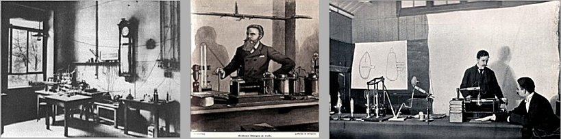 |
Discovery of X - radiation .
Left: Laboratoy of W.C.Röntgen in Würtzburg. Middle:
Röntgen shows off its X-rays. Right:
X-rays were independently of Röntgen
at the same time discovered also by H.Jackson and
A.A.Campbell-Swinton, but they did not deal with medical
applications. |
Immediately after his discovery of penetrating
radiation emanating from the cathode ray tube in 1895, Roentgen
himself took the historically first X-ray image on a photographic
plate, namely his wife's hand (Fig.3.2.1 on the right, even with
a ring). Both Roentgen and other physicians have been aware from
the beginning of the great importance of newly discovered
radiation for medicine. Roentgen thus became the
first radiologist...
Roentgen and other researchers initially
thought, that penetrating radiation originated in the diluted gas
of the cathode ray tube. In further experiments it was shown,
that the source of X-rays is not the discharge in the gas itself;
this ionization only supplies the electrons, that are accelerated
and their impact on the anode excite the
braking X-rays. The removal (exhaustion) of gas and the
use of a hot cathode emitting of electrons will
increase the efficiency of X-rays - vacuum X-ray tubes
have developed over the course of several decades (described in detail below).
Note:
A brief reflection on the extent to which the
discovery of X-rays was the result of chance or methodological
procedure, is given in §1.0 "Physics - fundamental
natural science", passage "Significant
scientific discoveries - chance or method?".
Fig.3.2.1. The principle of X-ray
diagnostics.
Left: Basic principal scheme of X-ray
imaging. Middle: X-ray spectrum emitted
from the the X-ray tube (filtered).
Right: The first X-ray image taken by
Roentgen himself - his wife's hands even with the ring (according to other sources, it was perhaps the hand of
his friend Prof. of anatomy A.Koelliker..?..).
Origin and properties
of the X-ray image
When using X-rays for imaging (especially in medicine), its basic
properties of penetrating even materials opaque
to light are used. The basic principal scheme of X-ray
transmission imaging is in the left part of Fig.3.2.1. The
penetrating electromagnetic X-rays with a photon energy of about
20-150
keV (wavelengths of about 5 to 50
picometers), generated in the X-ray
tube, pass through the examined object (organism
tissue), while part of the radiation is absorbed
depending on the thickness and density of the tissue,
while the remainder portion passes through the tissue
and is displayed either photographically or on a
luminescent screen, more recently using electronic detectors. In
the body, X-rays are most absorbed by bones, less by soft
tissues, least by body cavities and by air. When exposed to
X-rays, an X- ray image of the examined tissue
is created, which is a projection shadow image of density,
showing differences in density of tissues *). In
other words, an X-ray image is created by projecting X-rays from
the focus of the anode, through tissue structures within the
organism with different absorption coefficients and different
thicknesses, onto a film or imaging detector. Different
absorptions of X-rays in different tissues are assigned different
intensities in gray scale in the image; this assignment is
realized either in an analog manner (film blackening) or
digitally (electronic imaging detectors + computer, see below).
This creates an image reflecting the size, shapes and arrangement
of tissues and organs in the body, including possible changes
induced by pathological processes.
*) Differentiated
absorption of X-rays are the basis for formation of
X-ray image. This absorption depends on the layer thickness,
density and proton number of the irradiated substance. Soft
tissues have a lower density and lower absorption of X-rays -
more radiation is transmitted through these places, we get a
clearer image or greater blackening of photographic material. The
bones with calcium content are denser and absorb more X-rays -
less passes through it, we get a less intense image or less
blackening of the photographic film in these places. In Fig.3.2.1
on the right is an X-ray image on a photographic film.
X-rays interact with tissue atoms mainly through two
processes, discussed in more detail in §1.6, section "Interaction of gamma and X-rays": photoeffect and Compton
scattering (formation of electron-positron
pairs does not occur here due to the low energy of photons
used in X-ray diagnostics; an insignificant exception may be
portal and tomo-therapeutic images on radiotherapy irradiators,
see §3.6 "Radiotherapy"). Both of these processes are involved in the different
absorption of radiation in individual tissues (and also
in the different absorption in normal and pathological districts
within the same tissue), depending on the thickness, density of
the substance and the proton number of the atoms. X-ray
diagnostics is based on this different absorption of X-rays in
different tissues, as well as differences of absorbtion in their
physiological or pathological conditions.
Chemical
(atomic-elemental) composition of tissues and organs?
Different tissues and organs differ in their chemical
composition, which may or may not be
reflected in their different densities. If two adjacent
structures in the body have the same or close absorption
coefficient (linear attenuation
coefficient) for the X-rays used, they will
be indistinguishable from each other on X-ray images -
they will appear identical, even if their material
(chemical, elemental) composition is significantly different.
Differentiation or classification of different tissue types by
standard X-ray imaging is therefore very difficult and often
impossible.
A certain possibility of at least partial resolution
of the material composition of the displayed structures is
measurement - imaging - at different X-rays energies -
X-rays spectrometry. We will deal with these
possibilities below in the sections "Electronic X-ray
imaging detectors" - "Spectrometric
Photon-counting X-ray imaging", "X-ray
detectors for CT"
and "CT
with 2 X-rays - DSCT: Dual Source and Dual
Energy CT".
X-ray
image quality
Three parameters are important for high-quality X-ray imaging and
recognition of fine structures and anomalies :
¨ Sharpness
and resolution ability of imaging
For the projection image sharpness is important the small
size of the impact focus, from which the X-radiation is
emitted (see below, "The
design of the X-ray tube").
For classical X-ray diagnostics, the focus is about 0.5¸2 mm, but for
X-ray microscopy, an almost point focus with a diameter of the
order of micrometers is required. Closely related to sharpness is
the spatial resolution of the image *).
Sharpness and resolution can also be affected by the properties
of the imaging medium - photographic film, amplifying films,
electronic imaging detectors. The resolution of the X-ray image
is around 0.5-2 mm, depending on the size of the focus (at X-ray microscopy can be a thousand times better!).
*) Resolution is defined
as the smallest distance between two "point" objects,
at which they still displayed as two separate structures; or
equivalently as the half-width of the point object image profile.
At shorter distances, both objects already appear as one, they
are not distinguished. As in photography, resolution is often
measured in the maximum number of lines per millimeter
[lp/mm] that can still be distinguished; in practice, the real
X-resolution is around 2-5 lp/mm. The quality of X-ray imaging in
terms of real resolution is sometimes quantified in detail using
the so-called modulation transfer function MTF,
indicating using Fourier harmonic analysis, what details
of the examined object can be displayed with the given contrast.
The issue of resolution, contrast and recognizability of lesions
on X-ray images is largely similar to scintigraphic imaging - it
is discussed in detail in §4.2, section "Scintigraphic
image quality and detectability of lesions".
Significant deterioration in sharpness and resolution
occurs especially when the image is blurred due
to patient movement during exposure - motion blur.
With modern devices, this risk is minimized by shortening the
exposure time, thanks to the simultaneous increase the intensity
of X-rays. Also, the movements of certain structures inside the
body - heart beating or breathing movements - lead to image blur.
This adverse effect can be eliminated by gating (trigration) and
image synchronization in certain phases of cardiac pulsation or
respiration - ECG-gating, respiratory-gating.
¨ The contrast of
the imaging ,
which expresses the gradient of displaying differences in X-rays
absorption using a gray scale, is given by two factors. First of
all, it is the ratio of absorption coefficients for different
types of displayed tissue. It depends mainly on the differences
in the density of individual areas of tissue; where this
difference is negligible or non-existent, we can sometimes
increase it by applying contrast agents (see below). The
contrast in absorption further depends on the energy of the
X-rays. For thinner layers of soft tissue, soft X-rays
(approx. 20 keV) are more suitable, which interact mainly with a
photoeffect with a steeper difference in absorption depending on
density (the greatest contrast is achieved
for X-rays close to the binding energy of electrons on K or L
shells). Harder X-radiation (approx. 80-100 keV) is
required to display thicker layers and denser materials (eg
skeletal structure). Contrast in image is negatively affected by
Compton scattered radiation (see "secondary
diaphragms" below).
An important geometrical-anatomical factor,
significantly worsening the contrast of the X-ray image and the
overall recognizability of the lesions, is the cross-radiation
and superposition of X-rays from individual layers of tissues and
organs at different depths, generally with different densities.
This adverse effect is largely eliminated in CT imaging.
For digital
devices, the contrast can be additionally increased by computer
processing ( post-processing ) - a suitable brightness
modulation of the image. In such processing, the so-called bit
depth is important - the number of bits in which the
image is created in the process of analog-digital conversion.(ADC)
from an electronic X-ray detector to an image matrix in a
computer. When displayed, the bit depth indicates the maximum number
of shades of gray that we are able to display in the image -
the larger this number of shades of gray, the more depicted we
show particularly small differences in density and fine detail. A
higher number of bits in the image allows you to emphasize the
details in the image using suitable display windows for
brightness modulation - stretching a certain small range of
brightness values in the image to the full range.
The relationship
between the most commonly used bit depth b and the maximum
number of shades of gray is as follows (given by the power of 2 b
) :
2 bits = 2 shades (white and black only); 4 bits = 16 shades; 8
bits = 256 shades; 12 bits = 4096 shades; 14 bits = 16384 shades;
16 bits = 65536 shades; 24 bits = 16777216 shades.
Although a large number of shades (tens and hundreds of
thousands) are no longer directly distinguishable by the eye,
this allows by the use of narrow display windows to emphasize
density gradients.
¨ Number
of photons in the image - statistical noise
To obtain a quality well-exposed image, a certain optimal
number of X-ray photons is needed. In films and
luminescent screens, this number of photons is mainly determined
by sensitivity the material used, so that the
image is not underexposed or overexposed. With digital imaging
detectors, we can additionally adjust the brightness of the
image, but the image quality is still determined by the following
factor : X-ray
emission, its interaction and imaging detection is subject to
stochastic quantum laws, leading to quantum statistical
fluctuations in photon flux. With insufficient X-ray
photons, the image is "noisy", composed of disturbing
artificial brighter and darker spots and clusters of dots, where
fine structures and details can disappear. If we have the
registered number of N photons of X-rays in a given
element (pixel) of the image, then the local statistical
fluctuations - scattering, relative error - are SD = 1/ÖN. To obtain a
well-drawn image with statistical fluctuations of less than 3%,
more than 1000 photons must be recorded in each element of the
image, for 1% of the fluctuation there must be more than 10,000
pulses/element.
For digital imaging detectors - flat
panels (described below) - the quality of the X-ray image in terms of noise
depends on the sensitivity of the sensor: this is given by the detection
quantum efficiency DQE (Detection Quantum Efficiency),
which is the percentage of photons X-rays incident on the
detector, that are actually recorded by the detector and used to
create the image (the rest is uselessly
absorbed by the input window or detector material without
scintillation or electrical response). For
digital X-ray images, especially CT, the statistical noise of the
image is expressed in Hounsfield units HU (introduced below in the section "X-ray
tomography -CT", passage
"Origin of the density image"); in a good picture, the SD noise should not exceed
about 20-30 HU. The total number of photons for the exposure of a
given image is set by the product of the X-ray current and the
exposure time (see below "X-raytube", section "Braking X-rays")
- "milliampere-seconds"
[mAs]; it can also be electronically controlled using automatic
exposure - see below "Setting X-ray parameters".
¨ Artifacts
on an X-ray image
Under certain circumstances, some structures that do nothave
their origin in the displayed object, may appear on X-ray images
- they are false artifacts . They can be caused
by inhomogeneities, defects or impurities on the photographic
film or reforcing foils, inhomogeneities in the flat-panel
detectors, unwanted objects (eg metal) in the X-ray beam. In CT
imaging, so-called structural artifacts may occurs,
arising during the reconstruction of transverse sections in
places with sharp differences in density, especially at the
transition of bone and soft tissue.
X-ray
tube
Source of X-rays for X-imaging is a special vacuum tube called X-ray
tube or X-ray lamp. From an electronic point of view,
the X-ray tube is simply a classic diode
connected in a circuit with a high voltage of approx. 20-200 kV.
So it has two metal electrodes :
-->
Cathode
formed by a thin metal wire wound into a narrow spiral. A metal
that is very resistant to temperature is suitable for the heated
filament of the cathode - it has a high melting point,
is strong and mechanically stable, and has a low output work of
electron emission. Tungsten is most often used, which
has a high melting point of 3300 °C. It is basically similar to
the tungsten filaments of classical light bulbs (but where it is the emission of light, not electrons).
An electric current (several Amperes) is applied to
this metal wire, which heats up the fiber to a
temperature of approx. 2000 °C. Thermoemission
then releases electrons from the metal - the heated cathode emits
electrons. The release of electrons occurs when, during
their thermal movement, the electrons acquire a kinetic energy
higher than the output work of the electrons from the
given metal. As the temperature of the metal increases, the
electron thermoemission density increases significantly. The
dependence of the thermoemission intensity J on the metal
temperature T is described by Richardson's formula :
J = F . T2. e-w/(k.T) ,
where J is the current density of emitted electrons [A/cm2] -
current per unit area of the emitting surface of the metal, T is
the absolute temperature of the metal [°K], w is the output work
of electrons [eV], k=8.62.10-5 eV/° K is Boltzman's constant.
Electron emission has the character of a quantum tunneling effect
(§1.1, passage "Tunneling effect").
F is a material-dependent constant [A/(cm2.°K2)], for tungsten
it has a value of F~ 60 A/(cm2.°K2). The output work of
electrons from tungsten is w=4.5 eV and it starts emitting
electrons when heated to a temperature higher than 2000 °C, but
effective emission only occurs at temperatures of 2300-2500 °C.
For the X-ray cathode, instead of pure tungsten, a thorium-coated
tungsten filament is sometimes used, which has a lower electron
work function of only 2.6 eV. The cathode from this thoriated
tungsten effectively emits electrons already at a temperature of
1700-1900 °C. The lower operating temperature extends the life
of the cathode by about three times.A metal that is very
resistant to temperature is suitable for the heated filament of
the cathode - it has a high melting point, is strong and
mechanically stable, and has a low output work of electron
emission. Tungsten is most often used, which has a high melting
point of 3300 °C. It is basically similar to the tungsten
filaments of classical light bulbs (but where it is the emission
of light, not electrons).
An electric current (several Amperes) is applied to this metal
wire, which heats up the fiber to a temperature of approx. 2000
°C. Thermoemission then releases electrons from the metal - the
heated cathode emits electrons. The release of electrons occurs
when, during their thermal movement, the electrons acquire a
kinetic energy higher than the output work of the electrons from
the given metal. As the temperature of the metal increases, the
electron thermoemission density increases significantly. The
dependence of the thermoemission intensity J on the metal
temperature T is described by Richardson's formula:
J
= F . T2 . e-w/(k.T)
,
where J is the current density of emitted
electrons [A/cm2] - current per unit area of the emitting surface of the
metal, T is the absolute temperature of the metal [°K], w
is the output work of electrons [eV], k=8.62.10-5 eV/°K is Boltzman's
constant. Electron emission has the character of a quantum tunneling
effect (§1.1, passage "Tuneling
effect").
F is a material-dependent
constant [A/(cm2.°K2)], for tungsten it has a value of F~ 60 A/(cm2.°K2). The output work of
electrons from tungsten is w=4.5 eV and it starts emitting
electrons when heated to a temperature higher than 2000 °C, but
effective emission only occurs at temperatures of 2300-2500 °C.
For the X-ray cathode, instead of pure
tungsten, a thorium-coated tungsten filament is
sometimes used, which has a lower electron work function
of only 2.6 eV. A small amount of thorium, mixed into tungsten,
in a wire heated to about 2500°C, drifts to the surface layer,
where it causes more efficient thermoemission of
electrons. The cathode from this thoriated tungsten effectively
emits electrons already at a temperature of 1700-1900 °C. This
lower operating temperature extends the life of the
cathode by about three times.
If there were
no positive voltage on the anode, these emitted electrons would
form an electron cloud around the cathode and their
repulsive force would prevent further thermoemission (this is the case around the filament of a light bulb). However, at a sufficiently high positive voltage
(>60kV) at the anode, thermoemission electrons are
continuously diverted away from the cathode and rapidly move
towards the anode, an electron cloud is not formed. However, if
the anode voltage is relatively low (<40kV), part of the
emitted electrons will no longer reach the anode and a larger or
smaller electron cloud remains around the cathode, preventing
stronger thermoemission of electrons. Stronger heating of the
cathode no longer leads to higher thermoemission and to a greater
electron current through the X-ray.
Cathode in the shape of a flat emitter
Some new X-ray tubes instead of the classic spiral fiber have a
heated cathode using the so-called flat emitter
technology. It consists of a rectangle of heated thin sheet,
masked by several holes. By setting a negative voltage between
the cathode and emitter slits, a very sharply localized incident
focus on the anode can be more accurately achieved.
-->
Anode
Electrons emitted from the cathode are attracted to the anode
*) with a high positive voltage, while they are accelerated
by a strong electric field to the kinetic energy E = U.e, given
by the high voltage U between the cathode and the anode
(ie E = approx. 20¸200 keV). Just before the impact on the anode, it
obtains an electron with charge e and mass me a very high velocity
v = Ö(2.e.U/me) (for voltage U = 60kV, the electrons will have a kinetic
energy of 60keV and an impact velocity of approximately
150000 km/s, which is half the speed of light). Upon impact with the anode, the electrons brake rapidly,
converting some of their kinetic energy to hard electromagnetic
radiation - X-rays of two types: bracking and characteristic
radiation (the origin and properties
of these two types of radiation are discussed below). This X-ray leaves the anode and flies out of the tube
(Fig.3.2.1 left).
*) The anode, the electrode located
opposite the cathode, was formerly also called anticathode,
especially in the cathode ray tubes.
The anode
is made of a heavy material (most often tungsten), which has a
high electron density, so the incident electrons are sharply
braked by a large repulsive force, which, according to the laws
of electrodynamics, turns part of their kinetic energy into
braking electromagnetic radiation - X-ray photons. However, the
efficiency of this process is relatively small - only about 1% of
the total kinetic energy of electrons is transformed into X-ray
photons, the rest is converted into heat. The reason is that only
about 1% of electrons penetrate deep enough inside the atoms of
the anode material, up to the L or K shell, only where large
Coulomb electric forces act, causing a sharp change in the speed
of the electrons and thus effective excitation of hard braking
ratiation. The other electrons transfer their kinetic energy to
the electrons and atoms of the crystal lattice, which results in heat.
Note: The X-ray tube can be considered
the simplest particle accelerator (§1.5
"Elementary particles", part "Charged particle accelerators") - it is a linear electrostatic accelerator of
electrons, the source of which is a hot cathode, the (inner)
target is the anode, the braking (+characteristic) X-rays comes
out.
X-ray tube volt-ampere
characteristic
For the electronic operation of the x-ray tube, it is important
how the electron current [mA] by the X-ray tube depends on the
anode voltage [kV] - the volt-ampere characteristic -
and also on the incandescent current [A] of the cathode.
When the cathode is heated (e.g. with a current of approx. 5A, to
a temperature of approx. 1500 °C), as the anode voltage
increases, the electron current through the cathode gradually increases
(still more electrons from the cloud around the cathode reach the
anode) and then reaches saturation - all electrons
released by thermoemission fall on anode and there are no more
free electrons that could fly to the anode at a higher anode
voltage.
The cathode current
characteristic of the X-ray tube is also important - the
dependence of the resulting electron anode current on the cathode
glow current. This characteristic is different at
different anode voltages. Generally, as the glow current
increases, the anode current also increases initially, but only
up to a certain value. At a low anode voltage (<40kV), saturation
occurs - increasing the glow current no longer leads to an
increase in the anode current: the electric potential is not
sufficient for all thermo-emitted electrons to fly to the anode,
an electron cloud is formed around the cathode. Only at
a high anode voltage (>60kV) do all the electrons released by
thermoemission fall on the anode and the effect of the electron
cloud and saturation does not occur.
--> 3rd electrode - grid ?
In addition to the cathode and anode, in some types of X-ray
tubes, we can rarely find a third electrode - a wire grid,
located between the cathode and the anode, in close proximity to
the cathode. The electrical voltage applied to this grid very
sensitively modulates the flow of electrons (i.e. anode
current) and thus also the intensity of X-radiation. Applying a
higher negative voltage to the grid can very quickly interrupt
the anode current and thus the emission of X-rays (sometimes used
for fast x-ray cinematography).
Braking
X-rays
Braking radiation is a consequence of the laws of Maxwell's
electrodynamics, according to which every uneven
("accelerated" or "decelerated") movement of
an electric charge emits electromagnetic waves - see §1.5 "Electromagnetic field.
Maxwell's equations.",
Larmor's formula (1.61 '), monograph "Gravity,
black holes and space-time physics". Therefore, even when the electron is braked
after hitting the anode, the sharper the braking (the greater the deceleration a in the mentioned
formula), the more intense and harder the
electromagnetic radiation is generated -
see also §1.6, passage "Braking
radiation".
The effective
cross section for the production of braking radiation is
generally given by the highly complicated Bethe-Heitler
formula (derived from quantum
radiation theory, corrected by the Sauter and Elwert
factors of the Coulomb shielding of the electron shell). For a not very wide range of kinetic energies Ee of incident electrons
(tens to hundreds of keV) and proton numbers Z of target material (medium to
heavy materials), the overall efficiency of brake
radiation production h
can be approximated by a simplified formula :
h = E e [keV] . Z . 10 -6 [photons
/ electron] .
By converting the number of electrons ne to the current I = ne .qe/t and by substituting the value of the charge of the
electron qe
= 1.6.10-19 C (= 1.6.10-16 mAs) from this relation the resulting flux of
photons IX [number of photons /s.] braking radiation depending on
X-ray tube current I [mA] and anode voltage U [kV] :
I
X = U. I.
(Z /1.6). 10 10 [photons / s.] ,
which will be used below in the section "Setting X-ray parameters".
Only a relatively small part (only about 1%) of
the original kinetic energy of the incident particle changes to
braking radiation when braked in the matter. Most of the energy,
with multiple Coulomb scattering, is eventually transferred to
the kinetic energy of the atoms of the anode substance - it is
converted into heat.
Total energy spectrum of X-rays
(braking + characteristic), emitted from the anode of the X-ray tube, is drawn
below in Fig.3.2.5 at the top right. The graphic form of the
energy spectrum I(E) of continuous braking X-rays
is approximated by the so-called Kramers formula
:
I
(E) = K. I. Z . (Emax - E) ,
where I(E) is the relative intensity of energy photons E ,
K is a constant, Z is the proton (atomic) number of
the anode material, Emax is the maximum energy of X-ray photons, given by the
kinetic energy of incident electrons. It is clear that I(Emax) = 0 and the
formula is valid only for E < Emax .
It is logical that the efficiency of brake radiation
production is higher for high Z - large electric Coulomb
forces act around such nuclei, causing abrupt changes in the
velocity vector of the incident electrons that get close to the
nucleus. The efficiency of braking radiation [number of photons
/electron] increases with energy Ee incident electrons. Low-energy electrons are usually
scattered on the outer shells of the atoms of the anode material
and emit soft radiation, which often does not even reach the
X-ray energy range. The higher the energy of the incident
electrons, the more likely they are to penetrate deeper into the
anode atoms, close to the nucleus, where the greatest electrical
forces act, significantly changing the electron velocity vector,
leading to higher energy and efficiency of braking X-ray
production. However, the overall energy efficiency - the ratio of
the total energy of the emitted photons to the energy of the
incident electrons - is lower for higher energies (due to the
higher percentage of low-energy photons). And the heat losses in
the target (anode) are higher.
The braking X-rays produced by the X-ray tube have a continuous
spectrum from energies close to zero to the maximum
energy, given almost by the value of the anode voltage -
Fig.3.2.1 in the middle (here is the
spectrum after partial filtering of the softest component - see
below). The energy of the braking radiation
depends on the speed (acceleration) at which the electrons are
braked on impact with the anode surface. The individual electrons
penetrate at different depths into the atoms of the anode
material, thus emitting different wavelengths or energies of
photons. Those electrons, which "softly" brake with
repeated multiple scattering on the outer electron shells of the
anode atoms, emit a series of photons of low-energy braking (and characteristic) radiation;
some of them fall into the area of soft X-rays, others into the
area of UV and visible light (this
resulting low-energy photons are often absorbed in the anode
material and do not fly out). The deeper
the electrons penetrate into the interior of the anode atoms, the
closer to the nucleus, the faster the intense Coulomb forces
change their velocity vector and the harder the braking X-rays
are produced. The shortest wavelengths arise for electrons that
have penetrated to the level of the K shell and closer to
the nucleus, where they can be braked almost on-time. Depending
on the impact factor of individual electrons relative to the
anode atoms, which is random, all possibilities are
continuously realized - such a different degree of electron
braking causes a mixture of radiation of different wavelengths or
photon energies - the result is a continuous spectrum
of braking radiation. Low-energy X-ray photons are the most
represented in this continuous spectrum, only a very small
percentage at the end of the spectrum corresponds to high
energies, close to the energy of incident electrons, given the
high voltage between the cathode and the anode of the X-ray tube (see Fig.3.2.5 below).
The
wavelength and energy of X-rays
By its nature, X-radiation are electromagnetic waves of
short wavelength of about 10-9-10-11 m, which, however,
are emmited as quantum - photons - with an
energy of about 5keV-200keV ( "The particle-wave duality"). Earlier (until the 1960s) it was customary to
characterize X-rays with a wavelength of l and in the older
literature was given the so-called Duan-Hunt relation lmin [nm]
= h.c/e.U @ 1.234/U [kV] between the voltage U
[in kilovolts] at X-ray tube and the minimum wavelength lmin [in
nanometers] of the resulting braking X-rays *). A Kramer's
formula for the spectrum was given in the form I(l) = K.Z.I.[(l/lmin) - 1]/l2 (in
this form it was compiled by H.A.Kramers in 1923; at that time
X-rays were described only by wavelength).
This manner was very disadvantageous
and misleading, especially in relation to the creation mechanism
of this radiation in X-ray tubes, where the values of the
accelerating voltage in [kV] occur. Now is abandoned
long ago, the X-ray spectrum is expressed fundamentally by the photon
energy EX [keV], which in X-ray tube is derived directly
from the voltage U (maximum energy EXmax @ U, mean energy <EX > » U/3] and the Duan-Hunt relation has lost its importance.
*) The Duan-Hunt formula actually just a
differently written relation EX = h /l between the energy of the photon EX in [keV] and the wavelength l in [nm] for the situation,
when all the kinetic energy E = U.e of the electron of charge e
, accelerated by the voltage U, is converted into a photon
X-rays (corresponds to the energy EXmax and the
wavelength lmin ).
Characteristic
X-rays
In addition to braking X-rays with a continuous spectrum, a
certain smaller amount of characteristic X-rays
with a line spectrum (characteristic pair of peaks Ka, Kb) is emitted, the
energy of which does not depend on the anode voltage, but is
given by the anode material; for the most
commonly used tungsten, these are the 59.3+67.2 keV peaks (and
also the L peak around 10keV), which appear as "bumps"
on the continuous curve of the spectrum (Fig.3.2.1 in the
middle).
The
characteristic X-rays are caused by two processes :
¨ Direct process of the impact photoeffect
at the internal energy levels of the electron shell in the atoms
of the anode material - fast electrons penetrate into the atoms
and eject bound electrons from the K and L shells.
When electrons jump from the L shell to the emptied shell K
(K-series), or from the shell M to L (L-series),
the difference of energies is then radiated in the form of
photons of electromagnetic radiation - characteristic X-radiation
(cf. also with Fig.1.1.3 in §1.1).
¨ Indirect process of photoelectric absorption of
braking radiation - braking X-rays, generated by the
above-mentioned mechanism during the braking of accelerated
electrons, interact with other atoms inside the anode substance,
among others by a photon photoeffect (described in §1.6, part " Interaction
of gamma and X-rays ",
Fig.1.6.3 left), emitting electrons from the inner shells,
followed by an electron jump and the emission of characteristic
X-rays, similar to the previous case.
The impact electron photoeffect and
the emission of photons also occur when electrons jump in the
outer shells, but the energy of these photons is low and this
radiation is covered by continuous braking radion at the
beginning of the spectrum.
A certain minimum (threshold) anode
voltage is required for the formation of characteristic X-rays,
higher than the binding energy of electrons on the K-shell of
atoms of the anode material (for tungsten
it is about 70keV, for molybdenum 20keV).
If the anode voltage is lower, only continuous braking radiation
is generated in the X-ray, and when the threshold voltage is
exceeded, the spectrum contains both continuous braking and peaks
of characteristic X-rays.
The proportion of characteristic X-rays in
the total spectrum of the X-ray tube depends on the anode
material and the anode voltage. For a tungsten anode, it is
approximately 30% at a voltage of 100 kV and only about 3% at a
voltage of 200 kV.
X-ray tube design
Unlike conventional electron tubes used in low-current
electronics, X-rays tubes have a relatively robust design
(they resemble screens or transmitter electron tubes in size),
given by two circumstances. On the one hand, it is a very high
voltage, reaching hundreds of kilovolts. The second
circumstance is thermal heating: electrons
incident at high speed on the anode convert only a small part of
their energy into X-rays, the vast majority of their kinetic
energy is converted into heat - the anode of the
X-ray tube is heated strongly. To dissipate this
heat, the anode must have a relatively massive construction; in
addition, anode rotation or cooling is used (described below).
One of the technical parameters is maximum power
of the X-ray tube [kW] - peak electrical power input of the X-ray
tube, which the X-ray tube can still "withstand"
without overheating and thermally damaging.
The most commonly used material
for the anode of an X-ray tube is tungsten, a
heavy and heat-resistant metal. To improve the thermal properties
of the anode, especially the heat capacity, rhenium-alloyed
tungsten (10%) is often used, or the anode is composed of several
layers - alloyed tungsten, molybdenum, graphite. For X-ray tubes
for X-rays around 20keV for mammography, the anode is made of
molybdenum.
X-rays tubes can be
divided into two main groups, which govern their design (+ the third group of special constructions listed
below) :
¨
X-rays tubes for industrial irradiation and radiotherapeutic use
,
which do not require focusing of electrons to an almost point
focus and which have a fixed (non-rotating) anode. High energy
and X-ray intensity are common requirements here; the anode is
actively cooled by the flow of cooling medium through its
interior.
¨ X-rays
tubes for X-ray diagnostics
with focusing of the electron beam into the focus and mostly with
a rotating anode (to prevent local
overheating of the focus). Below we will
deal mainly with these X-rays tubes for radiodiagnostics. The
anode target material is
mostly tungsten, for low X-ray energies (around
20-40keV) molybdenum is used as the anode
target material; the X - ray tube is additionally equipped with a
beryllium exit window - see below "X-ray
mammography".
¨ Special
types of X-ray tubes
Microfocus X-ray tube have an extremely small
impact focus of electrons on the anode, of the order of
micrometers. This is achieved by placing a special set of
electrodes (electron optics - "objective") between the
hot cathode and the anode, focusing electrons from the cathode
into a very narrow beam incident almost point on the
target-anode. They provide very high sharpness and resolution of
the image, but only limited power (intensity, fluence) of X-rays.
They are used for X-ray microscopy and CT defectoscopy (see below
§3.3, section "Radiation
defectoscopy").
For special purposes (especially
spectrometric and micro -X-rays), the X- ray tubes with a frontal
transmission anode (Target Transmission
X-ray Tube ) are constructed, where the beam of accelerated
electrons impinges on the thin front-located anode, the resulting
X-rays passing through the material of the thin anode to the
outside of the tube where it is used. It can also be designed as
the above-mentioned microfocus.
In addition to the usual tightly closed
(sealed) evacuated X-ray tubes, so-called open X-ray
lamps are sometimes constructed. They have a metal
casing that the user can open, replace the cathode filament and
anode material (tungsten, copper, molybdenum, etc.) as needed,
and close the tube again and evacuate.
Fig.3.2.2. Special microfocus X-ray tube with transmission anode
for X-ray microscopy
Historical
development of X-ray tubes
X-ray tubes originally evolved from discharge lamps,
which are gas-filled glass tubes with electrodes to which a
voltage of the order of hundreds of volts is applied. The next
stage was Crookes cathode ray tubes - discharge
lamps with very dilute gas, on the electrodes of which a high
voltage of the unit of up to tens of kilovolts is applied. The
classic radiant discharge practically no longer occurs here, but
the ionization of the atoms of the diluted gas releases electrons,
accelerated by a high voltage towards the anode - the cathode
radiation originated. In addition to the fluorescence of
the flask or inserted objects, there is also a secondary
penetrating photon radiation - X-rays (discovered by Roentgen and independently by other
researchers), braking and characteristic.
Cathode ray tubes also played an important role in atomic
physics, with their help J.J.Thomson discovered electrons, which
allowed them to penetrate the structure of atoms.
The first "cold cathode"
X-rays tubes were actually Crookes cathode ray tubes with
specially modified electrodes. An important milestone was the
creation of a vacuum X-ray tube with a hot cathode,
constructed by W.D.Coolidge in 1913 (shown in Fig.3.2.1 on the
left). Later, with increasing performance, the anode
rotation as well as other technical improvements and
special designs were added to X-ray imaging diagnostics (see
below). Experiments with X-ray laser sources are
currently being performed- whether the excitation of
characteristic X-rays in a high-temperature plasma generated by a
laser beam or braking X-rays on the impact of accelerated
electrons on a target. On the sidelines, we can note that the
most complicated special "X-ray tube" (sources of
X-rays) can be considered wigglers and undulators of
electron synchrotrons (see §1.5, section "Charged
particle accelerators").
Electron focusing, focal
point
In order to achieve good sharpness and
resolution of the projection shadow transmission image in X-ray
diagnostics, it is necessary that the X-ray beam comes from an
almost point source. In X-ray tubes for X-ray
diagnostics, the red-hot filament - a tungsten
spiral - is embedded in a recess or focusing slit of the
cathode, which has a negative polarity, so that its
repellent effect clusters electrons into a narrow strip *). After
acceleration by high voltage, the electrons then fall into a
relatively sharply localized place of the anode - the impact
focus, which has a rectangular shape due to the
elongated shape of the filament. Real, optical focus the
resulting X-ray is a geometric projection of this radiating
surface on the anode, i.e. the impact focus, into a plane
perpendicular to the beam of radiation used for imaging. The
originally rectangular impact focus is reduced in the
longitudinal direction due to the inclined, tilted surface of the
anode; its projection in the direction of the display has an
almost square shape, usually 0.5-2 mm in size.
*) These X-rays tubes usually have two
cathode fibers - shorter and longer. By switching the
heating current, one or the other fiber can be heated and thus
the size of the impact focus on the anode can be changed.
Some new X-rays tubes, instead of the classic
incandescent fiber, have an incandescent cathode solved by the
so-called flat emitter technology. It consists
of a rectangle of hot thin sheet metal, masked by several holes.
By adjusting the negative voltage between the cathode gap and the
emitter, a very sharply localized impact focus can be achieved
more precisely.
Asymmetry of the X-ray
beam from the focus, heel effect
In the first approximation, the X-ray is emitted from the impact
focus isotropically, with the same intensity in
all directions. However, some of the incident electrons penetrate
below the surface of the anode and the X-rays generated there are
partially absorbed and attenuated as they pass through the anode
material. This leads to a change in the shape of the radiation
pattern from the target at the anode, to a certain angular
asymmetry of X-ray beam emanating from the chamfered
anode: for an angle of about 30° in the direction of the
cathode, the radiation intensity is about 5% higher than in the
center (0°), in the opposite direction (to the anode disk) about
15% lower. This shaping of the radiation characteristics are
sometimes referred to as anode heel effect, some
"heel shape", "skew". This phenomenon may
manifest itself in some minor inhomogeneity of the
X-ray image, especially during exposures of
large imaging fields, or during X-ray mammography. This
inhomogeneity is smooth and gradual, so it does not interfere
with visual evaluation; however, digital evaluation is sometimes
computer-corrected.
Anode cooling and rotation
As mentioned above, the vast majority (almost
99%) of the kinetic energy of the electrons
hitting the anode is converted into heat. This
released heat must be effectively dissipated to prevent
overheating of the anode. At low powers, passive infrared
radiation from the heated anode to the surroundings is
sufficient. X-ray tubes for high performance (without focus, e.g. in industrial use) have an actively cooled anode - inside the
anode there is a cavity through which the cooling liquid flows.
In diagnostic X-ray tubes, electrons fall
into a small, sharply localized spot on the anode - the impact
focus - about 1 mm in size. At higher powers, this
impact focus on the anode can heat up strongly locally.
It is necessary to ensure that the temperature of the focus is
lower than the melting point of the anode material (usually tungsten). Local
overheating of the focus, where the electrons fall, can be
prevented by rotating the anode *): the cathode
is eccentrically placed in the X-ray tube, the anode in the shape
of a conical disk (about 5-10 cm in diameter) rotates
around the longitudinal axis, so that the electron beam always
falls to a different place the circumference of the anode, making
the heating and heat dissipation more uniform (Fig.3.2.3 left).
Although X-rays emanate from the same place - the focus, which is
against the stationary cathode, this place is due to the rotation
of the anode constantly formed by another physical part of the
anode disk; the heat is thus better dissipated in the anode
material.
*) Anode
rotation
Because the anode is located inside a high vacuum tube, its
rotation cannot be ensured by a mechanical transmission from the
outside (via the shaft). No bearing is so tight that no air
enters the tube over time - the vacuum would be broken. Rotation
of the anode is driven electromagnetically:
inside the anode neck of X-ray tube is mounted on the bearings a
metal cylinder connected by a shaft on the anode - serves as a rotor.
From the outside the X-ray tube are disposed coils supplied with
alternating current - those forming the stator,
giving the rotating magnetic field which, by
electromagnetic induction (eddy currents are induced in the
rotor), rotates by a roller and an anode inside the tube
(Fig.3.2.3 left). From an electromechanical point of view, such
an X-ray tube is actually a small asynchronous electric motor.
The rotation speed of the anode is usually 50Hz (3000 rpm), also
10-12,000 rpm is used for high power X-ray tubes. A certain
problem is the wear of the bearings on which the
anode rotor is anchored. These bearings are highly mechanically
and thermally stressed, they are inside the vacuum space out of
the possibility of maintenance and lubrication (only
"dry" lubrication with silver or lead metal powder is
used) - their wear is usually the main limiting factor of X-ray
tube life.
In some X-ray tubes, hydrodynamic lubrication
of bearings with a thin layer of suitable molten
metal is sometimes used (a kind of
"aqua-planing" of the shaft in liquid metal, with
minimal friction). One suitable metal is gallium, which
has a low melting point of about 130 °C and a sufficiently high
boiling point of 2204 °C, so that even at relatively high
temperatures of several hundred °C, the vacuum does not
contaminate its vapor. Furthermore, such a lubricating contact
surface in the bearing efficiently dissipates heat from the
anode. Before the actual operation, after switching on the
device, the bearing is first heated and only after the melting of
the lubricating metal does the rotation of the anode begin, which
is then maintained continuously even outside the exposure, until
the device is switched off. The bearing is heated and the
required temperature is maintained by the effect of eddy currents
induced in the rotor (these are the same eddy currents which, by
their interaction with the rotating magnetic field of the stator,
drive the rotation of the anode). Special so-called eutectic
alloys are also used to lubricate the anode bearing metals
which are liquid even at normal temperatures (eg gallium, indium
and tin in an alloy of suitable ratio, with a melting point of
-10 °C).
From a mechanical point of
view, the rapidly rotating massive anode behaves like a flywheel,
preserving its vector of rotational momentum. If we try to tilt
the X-ray tube with a rotating anode (change the direction of its
axis), due to the gyroscopic effect, the
rotating anode puts up resistance and its bearings are
stressed by considerable forces. This is especially the
case with CT tomography devices, where the X-ray tube orbits
around the examined object relatively quickly. Therefore, X-ray
tude with double-sided anchoring of the anode axis
are sometimes used here. The shaft of the rotating anode, passing
through the whole X-ray tube, is mounted in bearings at both
ends. The cathode portion of the X-ray tube then has two
protrusions: one on the side for mounting and feeding the
eccentrically located cathode, the other in the middle for
mounting the second anode bearing. When the rotary anode shaft is
anchored on both sides, the gyroscopic forces are distributed and
the bearings are significantly less stressed.
Fig.3.2.3. Design of X-ray tubes used in radiodiagnostics.
Left: Classic X-ray lamp with rotating
anode. Right: X-ray tube rotating as a
whole (STRATON type), with the front anode in direct contact with
the oil cooling bath and with the magnetic deflection of the
electrons from the cathode.
Although the rotation of the anode prevents
local overheating of the impact focus on the anode, during longer
operation the anode heats up strongly as a whole and this heat
is only slowly transferred by infrared radiation through
a vacuum out of the X-ray lamp to the cooling medium. It is
therefore necessary to observe certain time delays between
individual exposures in order for the anode to cool down. Another
disadvantage of the rotating anode is the wear of the bearing
inside the vacuum flask, which cannot be lubricated or otherwise
maintained from the outside. In addition, when the bearing wears,
unwanted fumes are released into the vacuum space of the X-ray
tube.
X-ray tubes rotating as a whole
For higher performance, a new construction arrangement of the X-ray
tube rotating as a whole, with direct cooling of the
anode, was therefore developed. A beam of accelerated electrons
from an axially positioned cathode, deflected by the magnetic
field of the deflection coils (located outside the tube) *)
impinges peripherally on the opposite front anode, which is in direct
contact with the cooling oil bath from which the X-ray
tube is immersed - Fig.3.2.3 on the right. The resulting heat
from the impact focus is thus immediately dissipated away.
The X-ray tube rotates as a whole around its
longitudinal axis connecting the cathode to the center of the
anode, the X-rays emanating in the lateral direction (similar to
a conventional Coolidge-type tube). The heating and anode voltage
is conducted to the X-ray tube by means of collecting rings, on
which electric brushes slide (slip-ring
technology, similar to that of electric motors for direct
current). The main advantage of this design
is the substantially better cooling of the anode,
which is in direct contact with the cooling medium, while there
are no mechanically moving parts inside the vacuum space. The
bearings on which the entire X-ray tube is mounted are easily
accessible and can be effectively lubricated. This leads to the
possibility of achieving higher performance and significantly extending
the life of the X-ray tube.
*) The current through the deflection coils
must be precisely set depending on the accelerating anode
voltage: the higher the voltage [kV] at X-ray tube is set, the
higher the current must flow through the deflection coils so that
the electron beam is properly bent and hits the desired location
at the anode edge. By electronic control of the current in the
deflection coils, it is thus possible to set the desired position
of the impact focus of the electrons on the anode. By
controlling the deflection current, it is possible to define several
foci that can operate simultaneously in multiplex
operation.
Furthermore, X-ray tubes of this
design can be significantly smaller and lighter
at the same or higher power than conventional X-ray tubes with a
rotating anode. This is very advantageous in new technologies of high
- speed multi-slice CT devices,
where the rotational mechanics are strongly stressed by
centrifugal, gravitational and gyroscopic forces. The first type
of X-ray tube rotating as a whole (rotating envelope tube) is Straton
(developed by Siemens in 2004).
High performance x-ray tubes with
rotating anode
Another newer type of X-ray tube is Vectron (from the same manufacturer), with
high performance - max. anode current 1300mA at voltage up to
90kV and 800mA at 150kV. Unlike the Straton, it reverts to
Coolidge's earlier classic design of a fixed X-ray tube with a rotating
anode, with bearings lubricated by a molten metal
eutectic alloy. The anode has a high heat capacity and is
cooled by infrared radiation through the vacuum into the cooling
medium. Instead of oil, water is used as a cooling
medium (high voltage sources - generators -
are also cooled with water), which has a
higher specific heat capacity than oil. The cathode is formed by flat
emitter technology. It has a very small focus on the anode
of 0.4×0.5 mm, independent of the kV setting, even at high X-ray
power. The electron beam is deflected electronically very quickly
(4000 times per second) and creates two foci in the multiplex mode (this creates two overlapping projections in the z-axis).
Also other manufacturers supply
high-performance high-resolution X-ray tubes - GE (Performinx
HDw), Philips (iIMRC), Toshiba (Megacool Vi).
Electric
power supply of the X-ray tube
The X-ray
tube, as an electronic source of radiation, requires an
appropriate power supply, supplying electrical
energy generating X-rays and providing other functions necessary
for the correct operation of the device. The X-ray tube has three
basic power supplies :
¨ The heating current source
for the X-ray tube cathode. It is a heating transformer,
they supply a low voltage of usually 6-12V and a current in the
range of approx. 0.5-10 A on their secondary winding, with the
possibility of continuous regulation (see below "Setting the
X-radiation parameters").
Fig.3.2.4. Electric power supply of X-ray tube
Above: High anode voltage source. Middle:
AC voltage for anode rotation. Bottom:
Cathode heating voltage.
Note:
This arrangement of X-ray tube under high voltage, with a hot
cathode, rotating anode and X-ray emission I practically show on
the "work table" as an experimental demonstration.
¨ High
voltage source
- anode voltage for accelerating electrons in
X-ray tube. This is a voltage in the range of mostly about
20kV-150kV; it can also be lower for special X-ray machines for
spectrometric use, and up to 400 kV in industrial applications.
The basis of this source (also called a generator) is a high-voltage transformer, which transforms
the mains voltage (220V/380V) upwards - either directly from the
mains voltage to the required value, or more recently via an
electronic oscillating circuit. The high-voltage transformer has
a high conversion ratio (given by the ratio of the
number of turns on the primary and secondary windings) of the
order of 1000 or more.
Newer devices use high-frequency sources high
voltage. The mains voltage is first rectified and smoothed. This
DC voltage is supplied to the high-frequency oscillator
(inverter), which uses thyristors to generate an AC voltage of
about 10kHz with sharp edges. This is then in the high voltage
transformer converted to high AC voltage, which is further
rectified and smoothed (see below). The advantage of this
solution is that the high-frequency transformer can have
significantly smaller dimensions and weight at the same power
than a conventional transformer with a frequency of 50Hz. This
high-frequency oscillator and transformer solution, enabling
highly efficient transformation of electrical energy - power,
current, voltage - is called an inverter in
electronics.
The value of the anode voltage can be regulated
either continuously or stepwise in suitable steps. This is
achieved using an autotransformer which is preceded
before a high voltage transformer. The autotransformer regulates
the mains voltage in the range of approx. 20-220V, which is then
multiplied by the high-voltage unit by a constant ratio (approx.
1: 1000). In the case of electronic high-frequency sources, the
high-voltage regulation is carried out by means of frequency
control.
The AC high voltage is rectified by
vacuum or semiconductor diodes. The simplest rectification is one-way
("single- pulse") by means of one diode
connected in series (or without
rectification, the rectification is performed by the X-ray tube
herself *), when the emission of radiation occurs only in the
positive half-period of alternating current.
*) In fact, the X-ray tube
itself is basically a diode that can take care of the
rectification itself. For older and simpler devices, therefore,
the X-ray tube was supplied with alternating voltage,
while the emission of X-rays occurs only in half-periods when
there is a positive voltage at the anode. The disadvantage of
this solution is the increased proportion of the soft component
of radiation (arising at the beginning and end of the
half-period, when the instantaneous voltage is significantly
lower), and at higher powers also the possibility of reverse
current ("backfire") - in the opposite half-period, the
secondary electrons emitted from the heated focus of the anode,
can accelerate towards the cathode, which they bombard with high
kinetic energy and can damage it.
Two-way rectification
is more perfect ("two-pulse") using 4 diodes in a
bridge Graetz connection, or 2 diodes in a double secondary
winding, where there is always a positive (pulsating) voltage at
the anode and the X-ray tube operates in both half-periods of AC
voltage. In the past, sometimes a three-phase mains
supply of a three-phase high-voltage transformer is used
and 6 diodes in a bridge connection are used for rectification -
only a slightly pulsating DC voltage is generated (which never
drops to zero, but only by about 15% of the peak voltage), the
pulsations have a frequency of 300Hz; it is sometimes referred to
as six-pulse smoothing. A three-phase high-voltage
transformer can have two triple secondary coils, phase-shifted by
60°; after rectification by means of 12 diodes in a bridge
circuit, only a slightly pulsating DC voltage is obtained (with a
frequency of 600Hz it fluctuates only by about 4% - "12-pulse
smoothing"), close to the right smoothed DC voltage.
All these cumbersome solutions of heavy current
electrical engineering are already abandoned here, in principle high-frequency
(HF) high-voltage sources are used. With these high-frequency
high-voltage sources, capacitor smoothing can be performed very
well after rectification, thus obtaining a minimally pulsating DC
voltage (with a high frequency of only small pulses).
The value of high voltage on X-ray
tube is expressed in thousands of volts - kilovolts [kV].
If a pulsating voltage is applied between the anode and
the cathode of the X-ray tube, the maximum energy of the emitted
X-rays is given by the maximum positive value of the anode
voltage, which is expressed as [kVp] -
"number of kilovolts in
the peak".
¨ Power
supply for anode rotation ,
which is an alternating voltage (in the
simplest case mains 220/380V), applied to the stator
coils, creating a rotating magnetic field for
X-ray anode rotation. At a mains voltage frequency of 50Hz, the
fundamental frequency of rotation of the anode is 3000rpm; by
segmenting the stator coils, lower speeds of 1500, 1000, 750, 600
rpm can be achieved. To achieve higher speeds, the X-ray stator
must be powered by an electronic oscillator, providing a
frequency higher than 50Hz. A higher starting voltage is
first applied to the stator, which is reduced to about 1/3 after
spinning to maintain synchronous speed. The speed of the anode
(rotor) can be electronically monitored on the basis of the
current flowing at a given voltage through the stator coils when
the rotating magnetic field is excited (after reaching the
synchronous speed this current decreases significantly). Only
after the anode has been rotated to the required speed can the
high anode voltage start and the exposure begin. In order to
prevent the X-ray anode from rotating unnecessarily for a long
time, the opposite phase of alternating voltage is connected to
the respective stator coils for a while after the exposure,
whereby the rotating magnetic field reverses its direction and
the rotation of the anode is electromagnetically braked (for some types, a separate winding is installed in the
stator for braking, a DC supply for magnetic braking of the rotor
is also used). Exceptions are anodes with
molten metal (gallium) lubricated bearings, which rotate
continuously, even between exposures, as described above.
Current X-ray devices also use other electronic
power circuits to supply electric motors for sliding and
rotating movements, X-ray tubes cooling, as well as control and
regulation electronics, including detection and evaluation
circuits.
X-ray
tube cover
During actual operation in X-ray machines, the X-ray tube is
encapsulated in a special metal cover (made of
aluminum alloys) of cylindrical shape *). The cover is shielded
from the inside by lead sheet approx. 3 mm before unwanted
penetration of X-rays into the surroundings. At the ends of the
housing there are bushings through which voltage is
applied between the anode and the cathode by means of
well-insulated high-voltage cables, and a low heating
voltage is then applied at the cathode end. In the middle part *)
of the cover there is an exit window (of course
unshielded, to which the X-ray tube must be turned with its
impact focus) made of a light material, mostly acrylic glass,
through which the X-ray beam comes out for the respective use. In
power X-rays tubes, the space between the X-ray lamp and the
walls of the package is filled with a cooling medium -
transformer oil. The oil environment also increases the electrical
strength of circuits - prevents high voltage electric
shocks. To eliminate the mechanical stress on the cover due to
the thermal expansion of the cooling oil, a rubber expansion
membrane is built in a suitable place on the wall of the
X-ray tube cover (prevents, for example,
the cover from bursting when the X-ray tube overheats).
*) For Straton X-ray
tubes, the housing has a double cone shape and the exit window is
near the end where the anode is. The appropriate location of the
impact focus on the anode opposite the output window in the
housing is ensured by deflection coils (incl. the angle of their
rotation), located from the outside in the narrowed part of the
housing - Fig.3.2.2 on the right.
Smaller, low-power
X-ray instruments sometimes use a compact design:
a high-voltage transformer (for the anode) with a winding of
heating current for the cathode is built into the common housing
together with the X-ray tube. Only 220V mains supply is then
conduct to such a compact system.
Collimation
and localization system
The following is a collimation system,
consisting of a tubus with adjustable orifices defining the
geometric shape of the X-ray beam. The apertures are adjusted so
that the X-ray beam covers only the displayed area and other
parts of the body are not unnecessarily irradiated. For visual
localization and adjustment of the displayed field a light
navigation system is installed in the X-ray tube
collimation system - the light from the filament lamp or LED is
guided by optical projection through the collimation system so as
to achieve a conformity between the visible light field and the
X-ray field. Before the examination, it is possible to adjust the
position of the displayed field on the film cassette or display
panel, as well as on the surface of the patient's body.
Mechanical design of
X-ray devices
The cover with X-ray tube and collimation system, together with
the opposite film cassette or imaging panel, are mounted on
special stands of several types and
constructions, according to the required X-ray imaging
methodology - Fig.3.2.5. For skiagraphic imaging,
the X-ray is most often mounted on top of a vertical
stand (column tripod mounted
on the floor or ceiling mount) with the possibility of easy
mechanical movement. The film cassette or display panel is
mounted at the bottom of the stand, again with the possibility of
sliding. Between them is a sliding bed with the patient for
examination while lying down. For standing (or sitting) imaging,
the X-ray tube with the collimation system is rotated
horizontally, the opposite cassette or flat-panel is on a
separate vertical stand (so-called vertigraph). The
horizontal movement (travel) of the X-ray tube can be realized by
means of rails mounted on the ceiling or floor
of the examination room. Displacements of individual parts of the
X-ray system can be manual or motorized,
using electronically controlled electric motors. For new systems,
the so-called autotracking is implemented -
automatic synchronous coupling of display panel and X-ray tube
displacements (equipped with a collimation system). Some systems
for sciagraphy and sciascopy have the ability to turn or tilt the
X-ray stand, imaging panel, and the bed for various
angles, from horizontal to vertical - such a system is
called an X-ray tiltable wall and has a wide
range of uses.
For flexible sciascopic
imaging, the X-ray tube and the opposite
imaging detection system are often mounted on a special stand in
the shape of the letter "C" - the so-called C-arm
- Fig.3.2.3b., or the so-called U-arm -
Fig.3.2.3c. These arms can be rotated using
electric motors to different angles around the patient, allowing
flexible display in different projections. These systems (which
are sometimes mobile) are used in a wide range of applications,
such as digital subtraction angiography (see below DSA - Fig.3.2.3), X-ray navigation of
interventional procedures, afterloading in radiotherapy
(see §3.6, section "Brachyradiotherapy" - Fig.3.6.7) and others.
A separate category of X-ray device design
solutions is transmission X-ray tomography CT,
where the X- ray tube and the opposite electronic detection
system are mounted on a portal rotary stand - gantry
- described in more detail below "X-ray
tomography - CT", Fig.3.2.4. This
includes also special constructions of X-ray imaging devices,
installed directly on IGRT radiotherapeutic
irradiators (see §3.6, section "Isocentric
radiotherapy", Fig.3.6.1c) or tomotherapy
(§3.6, part "Modulation
of irradiation beams",
Fig.3.6.4a).
Further technical details of the
construction of X-ray devices and their accessories are already
outside the scope of this physically focused treatise...
X-ray tube aging and
damage
Like almost any device or electronic component, even X-ray tubes
can be subject to adverse changes due to "aging", load
and operational damage. Over time, material degradation,
vacuum, and wear of rotary bearings occur. Several types of
adverse changes in X-ray tube properties can occur :
--> "Burning out" of the cathode filament
The red-hot cathode, providing electrons by thermoemission, is
mostly made of tungsten wire, which is highly heat-resistant
(melting temperature is 3400 degrees). However, when annealing at
high temperatures, tungsten evaporates slowly, often unevenly, so
that the spiral can become quite thin in some places. This can limit
the life of the cathode spiral.
--> Violation
of the X-ray tube vacuum
Small leaks can occur between the glass and metal parts
of the x-ray bulb, allowing air to gradually enter the vacuum
environment of the x-ray tube over longer periods of time. From
the metal parts, especially from the heated ones, and from the
stressed rotary bearings of the anode, unwanted fumes also
evaporate and release into the environment of the X-ray tube.
--> Local
overheating of the impact focus on the anode
At high powers, the impact focus can be strongly locally
heated to temperatures briefly exceeding the melting
temperature of the anode material. This results in small
micro-damages, various pits and cracks. The production of X-rays
is then no longer perfectly homogeneous...
--> Wear
of the anode rotary bearings
The high temperature and rotation frequency lead to a large
mechanical load on these bearings. The wear of the bearings leads
to greater noise during the operation of the X-ray tube and
deterioration of the stability of the focus. Wear can be
prevented to a large extent by lubrication of the bearings,
in the case of high-performance X-ray tubes, lubrication using a molten
metal eutectic alloy is used.
Setting of X-ray parameters
To optimize X-ray diagnostics, it is necessary to set suitable
X-radiation parameters. In the electrical circuit of the X-ray
tube we can regulate and set two basic electrical parameters as
required (the third is only time, the
fourth is realized by mechanical arrangement) :
¨ Anode
voltage U [kV] ,
which is a high voltage supplied between cathode and anode,
determines the maximum and mean energy of the photons
of the resulting X-rays, its "hardness". The maximum
energy of X-rays in [keV] is numerically practically equal to the
anode voltage U in [kV], the mean energy is slightly
higher than 1/3 of the max. energy. With increasing anode
voltage, the whole spectrum of X-rays shifts towards higher
energies (shorter wavelengths) and increasing the relative proportion of higher
energies (harder short-wave components).
In practice, the anode voltage varies in a wide range
from about 20kV to 200kV (depending on the type of displayed
structures), in the industrial use of X-rays then higher.
Note: The energy - hardness - of
X-rays emitted is often referred to in X-ray jargon as the "quality"
of X-radiation.
¨ Anode current I [mA]
flowing through the X-ray tube, determines the intensity
(fluence) of X-radiation emitted by the X-ray tube IX. It is most easily
regulated by changing the heating of the cathode
- the glowing stream - and thus the temperature
of the cathode fiber. The glow current can be regulated simply by
means of a rheostat in the glow circuit (in the glow transformer circuit),
more recently with special electronic circuits equipped with
transistors and thyristors. At higher heating of the cathode
fiber, more electrons are emitted, a larger stream of electrons
flows through the X-ray tube and a higher intensity of X-rays is
emitted (but see "Volt-ampere
characteristics of X-ray tube"). The average X-ray tube current is in the range units
of mA to about 200mA, the peak current can be significantly
higher (in pulse mode). E.g. an X-ray tube with a tungsten anode
(Z=74) supplied with an anode voltage U = 120 kV at a X-ray tube
current of 1 mA emits X-rays with an intensity IX of approximately 6.1013 photons /s. (follows from the approximate relationship for braking
radiation production efficiency given above in "X-ray
tube", passage "Braking
X-rays").
¨ Exposure
is the total amount of X-rays photons, which determines the
quality of X-rays images and also the radiation exposure of the
patient. It is given by the product of radiation intensity IX (photon fluence /s.)
and exposure time T - it is therefore proportional to the
product of anode current by X-ray tube [mA] and exposure
time [s]: "milliampere-seconds" mA.s
= Q, which is the total charge
Q electrons or the electrical amount that passes
through the X-ray lamp during exposure (the
coefficient of proportionality h is given above in the
section "Braking X-rays"). At Q=
1 mAs, approx. 1013 of photons is radiated from the anode, of which only a
small part is used for X-ray imaging - of most photons flying in
different directions, only a relatively narrow conical beam is
selected by collimation, low energy photons are further removed
by filtration (see below).
Note: The energy
of X-rays does not depend on the magnitude of current, time or
electrical amount.
For the acquisition of common skiagraphic
images of soft tissues, the exposure to X-rays of about 2 - 6 mAs is used, for
the skeleton about 20 - 80 mAs, for CT even 200 mAs. In modern X-ray devices
capable of operating in a pulsed mode with high instantaneous
power, a high current value [mA] at a short exposure time [s] is
preferred to achieve the desired exposure [mAs] - thus reducing
the risk of blurring the image with patient movement.
Based on
empirical experience, the recommended value of anode voltage [kV]
and exposure [mAs] is determined for each type of X-ray
examination, providing a quality image of the required structures
at a relatively low radiation exposure. Some devices also use automatic
exposure, which electronically switches off the anode
voltage in the generator - and thus the exposure - after reaching
a certain preset "amount" of X-rays. For the purposes
of automatic exposure, the flux of transmitted X-rays is
monitored by means of ionization chambers placed behind
the film cassette or behind the flat panel. For digital imaging
detectors, presetting the total number of pulses stored in the
digital image can also be used to interrupt the exposure.
Similarly, exposure optimization works for CT instruments, where
according to the signal level from the detectors in the
pre-planning radiographic display of SPR (topogram), the optimal
current values [mA] can be automatically adjusted during
self-diagnostic scanning - ATCM (Automatic
Tube Current Modulation), see below "CT".
The already generated X-rays are subsequently treated by
filtration :
¨ Filtration, collimation
The soft X-rays of longer wavelengths and the low energy of
photons at the beginning of the continuous spectrum of
X-radiation are of no significance for diagnosis, they are
usually absorbed in the skin and shallow layers of tissue -
causing only unwanted radiation exposure. Therefore, it is
removed by filtration - an aluminum or copper
plate about 1.5-4 mm thick is inserted into the radiation path,
which absorbs the soft component of X-rays to a large extent,
while transmitting the harder component - see the shape of the
spectra in Figure 3.2.5. The initial partial filtration of the
generated X-rays is already created by passing through the
material of the anode, the glass flask of the X-ray tube, the
cooling oil, the material of the cover and the outlet window (thus the X-ray tube glass flask itself acts inherently
as a partial filter, equivalent to about 0.5 mm Al; similarly the
cooling oil and the X-ray tube cover window).
In some
special cases when we need sharper and more selective filtering
of certain areas of the energy, so used filtration K-edge
(K-edge filter). It is based on significantly increased
("resonant") absorption of photon radiation at
energy equal to or slightly higher than the binding energy of
electrons on the K-shell of atoms of the material used (see
§1.6, section "Interaction of
gamma and X-rays", Fig.1.64). By
combining a standard filter (Al, Cu) and a filter made of a
suitable heavier material using the K-edge effect, we
obtain a bandpass filter, selecting a certain section of
energies from a continuous spectrum of X-rays. This is especially
true for mammography, where a molybdenum or rhodium
filter cuts off photons of higher energies than about 20-23keV to
achieve better contrast (see "X-ray mammography"
below). Also for DEXA methods - analysis of absorption
using two X-ray energies (see below "CT with 2
X-ray tubes- DSCT: Dual Source and Dual Energy CT").
The geometric
delimitation of the X-ray beam is performed by collimation
(mentioned above) .
Fig. 3.2.5. Basic scheme of X-ray examination.
Left: Arrangement of X-ray tube,
filter, DAP-meter, primary and secondary diaphragm, film or
detector. Right: Energy spectra of
X-rays from X-ray tube, after filtration and after passing
through the patient.
Scattered
X-rays
When X-rays interact with matter, Compton scattering of
photons on free or weakly bound electrons occurs, among
other things. These scattered photons fly out of the tissue with
lower energy and in different directions. The
proportion of scattered radiation is greater the larger the
patient (and is also higher for harder X-rays from tube - higher
voltage [kV]). Scattered radiation degrades the quality
of the X-ray image - it reduces its contrast. The possibility of
suppressing scattered radiation is mentioned in the following
paragraph. This Compton-scattered X-rays further cause some small
radiation exposure even outside the X-ray beam
itself from the X-ray tube. This radiation exposure is not high,
scattering albedo of the human body for X-rays is less
than 1% (albedo was discussed in
§1.6, section "Interaction of radiation passing
through matter") . At a distance of 1 m, the radiation dose is about 0.1 mGy /1 mAs, in 2
meters only about 0.005 mGy /1 mAs. Nevertheless, during X-ray examinations,
radiation workers should not stay in the examination room during
the exposure, unless necessary, but in a shielded control room -
the exception is, for example, interventional radiological
procedures.
Filters
and apertures for X-ray imaging
In the practical diagnostic application of X-rays, it is
important to use filters and collimating screens - Fig.3.2.5.
Suitable primary apertures ensure the geometric
delimitation of the X-ray beam, reaching only the
necessary examined area (a sharp image with high spatial
resolution is ensured by the fact that the radiation comes from
an almost point focus on the anode by X-ray tube, as described
above). Immediately behind the X-ray tube is placed a primary filter,
most often made of aluminum sheet, which absorbs low-energy
photons (from the beginning of the continuous X-ray spectrum),
which are not usable for imaging (they would penetrate only into
the subcutaneous tissue) but would increase the patient's
radiation exposure (mentioned above). This is followed by a tubus with
adjustable diaphragms for the geometric
delimitation of the X-ray beam (size of the imaging field). A
thin plane-parallel ionization chamber is
usually mounted on the outlet window of the tube for monitoring
the exposure to X-rays, the so-called DAP meter (see below "Radiation load during X-ray examination"), allowing to determine the
radiation dose of the patient during X-ray examination -
Fig.3.2.5 top left.
A secondary aperture
is then placed between the patient and the film (or screen or
imaging detection system, flat panel). It is a lattice
formed by parallel or diverging absorption lamellae
(lead strips) which, through their gaps, transmit only primary
X-rays passed in the direction of the original beam, while
secondary Compton-scattered photons (moving in other directions)
are absorbed in the partitions. It is therefore a collimator,
which attenuates the radiation only minimally in the primary
direction, while the attenuation of the obliquely transmitted
scattered radiation is considerable. The quality of the secondary
screen is determined by the grid density (number of
lamellae per centimeter) and the grid ratio (the ratio
between the distance of the absorbent strips and their height).
Suppression of secondary scattered radiation significantly improves
the contrast of the X-ray image. On the other hand, the
secondary aperture also absorbs some of the useful X-rays (eg with a Bucky aperture, the attenuation is about 1.8
times), so it is necessary to increase the
exposure. Three types of secondary screens (grids) are used :
- Converging focused Bucky-Potter screen
(approx. 10 slats /cm). The Bucky
screen has relatively thick partitions (approx. 1 mm), which
would be projected into an X-ray image and have a disturbing
effect. This disturbing raster is eliminated by moving the
aperture during exposure, blurring its image and disappearing
into the overall background.
- Parallel fine Lysholm screen (40-60
slats /cm).
- Ultrafine Smith screen (density >100
lamellae /cm). Due to too high absorption,
it is not used in practice.
Terminological note: In radiodiagnostics, it is
often customary to use the not very precise generic name "aperture".
More precisely, however, these are collimators
and filters.
Visualization and recording of X-ray images
X-rays, carrying density information after
passing through the displayed tissue, is invisible
to us, so it is necessary to "make it visible"
or register it using suitable material and
electronic methods. There are basically three ways to display
this X-ray :
- Visual observation
of the image on a luminescent screen
A luminescent screen is a plate or
foil on which is coated with a layer of suitable material (such as zinc sulphide, .......),
in which fluorescence is produced upon
interaction with ionizing X-rays. Thus, we can see a projection
density image on the luminescent screen via X-rays. The advantage
of this simplest method was the possibility of continuous dynamic
observation - sciascopy. However, the main disadvantage
is the low sensitivity and high
radiation exposure of both the patient and the
radiologist...
- Imaging on
photographic film
Ionizing X-rays cause a photochemical reaction
in suitable photographic materials, mostly containing silver
bromide. This photographic emulsion, coating on the surface of a
plastic film, forms a photographic film in which
the incident X-rays form a latent photographic image - is
described in more detail in §2.2 "Photographic detection
of ionizing radiation". After
development, we receive a negative density photographic
image in X-rays.
- Scanning with an
electronic imaging detector,
which registers incident X-rays, converts it into electrical
impulses and, after procesing by complex electronic circuits,
creates digital density images in computer
memory - this most advanced method is described in more detail
below "Electronic
imaging X-ray detectors"...
Amplifiers and digital
sensors of X-ray image; indirect and direct digitization
Direct X-ray photographic film for
display belongs to the past, and is gradually replaced by more
sophisticated technologies. To increase the sensitivity
of the scanning X-ray suitable image enhancement
methods are used in the image, more recently methods of
electronic image capture. This makes it possible to significantly
reduce the required intensity of X-rays and thus the radiation
dose for the patient, as well as to reduce the undesired exposure
for radiation workers.
- Amplifying foils
During photographic skiagraphy, amplifying
luminescent foils are attached to the film, the task of
which is to convert X-rays into light, which is exposed by the
photographic film. It consists of a layer of phosphor dispersed
in an emulsion of gelatin or nitrocellulose. Use calcium
tungstenate (emits blue light), lanthanoxid bromide
(blue light), gadolinium-carryover (green light), barium
chloride (blue light)... The film has to be sensitized
to the color of the light from the phosphor. It is already
abandoned.
- Xeroradiography ,
where a positively charged semiconductor (selenium) plate is used
instead of film. The incident photons of X-rays there evoke a
photoeffect, in which the photoelectrons locally compensate for
the original positive charge - a latent electrostatic
image is created ; in the copier, powder particles of
dye are then attracted to differently charged places of the
plate, which are finally printed on paper where a visible image
is created. It is also abandoned.
- Memory foils
replace the film in the X-ray cassette and
retain a latent electron image after radiation exposure. The
sensitive layer usually contains europium atoms (BaFCl:
Eu2+, instead of Cl it can be
iodine or bromine). The impact of X-rays photons
excites in the sensitive layer of the film, electrons are
released from the europium atoms, which are trapped in the halide
metastable levels of so-called "electron traps"
- a latent electron image is formed . This
latent image is made visible after exposure by photostimulation
using a laser infrared beam: a "trapped" electron is
released into the conduction band, after which the electron is
captured on the excited surface in the luminescent center,
followed by deexcitation to baseline, accompanied by photon
emission of light. This light is registered by a sensitive
photomultiplier, the generated electrical pulses are sampled and
converted by an analog-to-digital converter into digital image
information. The device that reads and digitizes the latent image
is called a digitizer - it is an indirect
digitization of an X-ray image. It will be
temporarily used for some time...
- Image intensifiers
During sciascopy, the image on the fluorescent screen ("shield")
is amplified by a special image tube - image intensifier.
The light image created by the impact of X-rays photons on the
fluorescent screen of the inlet window of the tube causes a
photoelectric effect on the enclosed photocathode by its emitted
photons of visible light. The emitted photoelectrons are
accelerated by a voltage between the photocathode and the anode
(approx. 10-20 kV) and directed by electron optics to a second
luminescent screen, where they create a reduced inverted image,
but its brightness is more than 1000 times greater than the
original image. This image is then optically captured by a video
camera and displayed on a TV screen or computer monitor. It is
still used for older devices, new devices are already supplied
with digital flat-panels.
- Electronic imaging
detectors - flat panels
All of the above image amplifiers or television sensors are only
a temporary technical solution. New systems are equipped with an
electronic digital image sensor on a compact
so-called flat panel, consisting of a scintillator
(e.g. cesium iodide CsI: Tl or based on gadolinium Gd2O2S:Tb - GOS; see §2.4 of scintillators, the "Scintillators and their properties") and semiconductor optoelectronic amorphous
silicon (a -Si). The detection panel
consists of a large number of elements - cells, pixels,
assembled into an image matrix of about 2000 x2000 elements, and
more. The most perfect imaging detectors are semiconductor
pixel detectors (SPD), see §2.5 "Semiconductor detectors". The pulses from the individual elements of the
detector are stored in multiplex mode with the help of an
analog-to-digital converter (ADC) directly into the computer's
memory - they create a digital X-ray image. Only
this technology of so-called direct digitization
belongs to the future... - it was described in more detail below
in the section "Electronic X-ray
imaging detectors".
Note: The terminology
of "direct" and "indirect"
digitization is temporary and will be abandoned
soon: all X-ray images will be automatically primarily
digital (using of technology now
called "direct digitization").
Electronic imaging detectors of X-radiation
The former X-ray imaging using photographic film or a luminescent
screen is now generally being replaced by electronic
imaging detectors - Fig.3.2.6. The advantage is
significantly higher detection sensitivity and wide possibilities
of electronic and computer image processing (digitization). All
these imaging detectors are based on modern technologies called quantum
optoelectronics (photonics), which use an
internal or external photo effect to convert photons into
electrical signals.
¨ Image intensifier
Electronic imaging with image intensifier was
widely used in the 1960s - 1980s - Fig.3.2.6 left. The image
intensifier is a special vacuum tube with two windows - input and
output. On the inside of the inlet window is a layer of
scintillator (mostly cesium iodide) and below it a thin metal
layer of photocathode. The incident X-rays cause flashes of light
in the input scintillation layer, which by photoefect eject
electrons from the photocathode. The electrons thus generated are
then attracted by annular accelerating and focusing electrodes,
to which a high positive voltage is connected (gradually
increasing up to about 30 kV at the anode at the output
scintillator). This electro-optical system, acting as a
conjunctive "electric lens", throws electrons onto an
output scintillator (mostly ZnS: Ag), where the accelerated
electrons produce intense flashes. Thus created reduced, inverted
but very clear ("amplified", intense) image is then
captured by an optical TV camcorder and (analog) displayed on the
TV screen. Later, digital CCD camera imaging with computer image
recording was used. Image intensifiers or TV sensors were just
temporary technical solution, the future belongs to
fully digital X-ray image sensors - flat panels :
Fig.3.2.6 Electronic imaging detectors in X-ray diagnostics.
Left: X-ray acquisition using an image
intensifier. Middle: Flat-panel with
indirect (scintillation) and direct (semiconductor) conversion of
X-rays into electrical signals. Right:
Ring-arranged CT detectors with fast ceramic scintillators and
photodiodes.
¨ Flat - panels
Modern and more advanced electronic X-ray imaging detectors are
so-called flat panels ( flat
- they have the planar shape of a thin plate), which provide signals for direct digital X-ray image.
The detection panel consists of a large number of elements -
cells, pixels, assembled into an image
matrix of about 2000 x 2000 image elements, and more. The level of the
electrical signal from each pixel is proportional to the
intensity, resp. the number of X-rays photons incident on a given
location of the flat-panel. From electronic multiplex
registration circuits (multiple
read-out) the image signal via the ADC
is fed to the image matrix of the computer, in the individual
elements ( pixels) of which information about the
intensity of X-rays from the corresponding location of the
irradiated object is stored. In terms of the method of detection
and converting X-rays into electrical signals, flat panels of two
types are constructed :
- Scintillation
detection
(indirect conversion)
,
when photons of X-rays impinge first on the layer of scintillator
material (most commonly used cesium iodide CsI: Tl) *) in which
they evoke flashes of visible light (scintillators
and their use for the detection and spectrometry of ionizing
radiation is discussed in detail in §2.4 "Scintillation detection and gamma-ray
spectrometry"). This scintillation light then enters the semiconductor
photodiodes (mostly silicon - a-Si - amorphous silicon
is used as the semiconductor material), in which an electric
charge is released by the internal photo effect (electrons and
"holes") and the light is thus converted into an
electrical signal - Fig.3.2.6b. The term "indirect
conversion" here means, that X-rays are first converted
in the scintillation layer into visible light, which is then
converted into an electrical signal in the photodiodes. This flat
panel design is currently the most widely used.
*) Scintillation crystals of
some flat panels have a "fibrous" design. They are
composed of densely spaced thin vertical needles. This design
reduces the lateral scattering of light scintillations, leading
to a sharper image.
ISS technology
Some new types of flat panels with scintillation conversion have
a somewhat curious design with "opposite orientation"
with respect to Fig.3.2.6b: the displayed X-rays are coming
on the side of the layer of photodiodes and reading TFT
transistors, passes through this layer and then impinges on the
CsI scintillation crystal. Scintillation interactions then
usually occur in a layer near the photodiodes, thereby reducing
lateral scattering by scintillation and improving resolution.
This solution, referred to as ISS (Irradiated Side Sampling)
technology , is made possible by the electronic miniaturization
of the photodiode and reading circuit layer, which is thin
and has virtually no effect on the transmitted X-rays.
- Semiconductor detection (direct conversion) ,
where photons of X-rays fall directly into semiconductor
detectors (suitable material is CdTe, CdZnTe, or Si for
lower energy). Absorbed X-rays create
electron-hole pairs, electrons in a strong electric field drift
to the anodes, where they generate short electrical pulses
(approx. 10-9 s). The amplitude of these pulses is proportional to
the energy of the absorbed X-ray photons. Thus, photons X release
electric charges through their interaction and are directly
converted into an electrical signal (the
general principle of semiconductor detectors is given in §2.5
"Semiconductor detectors") - Fig.3.2.6c. They are
also constructed in smaller dimensions (in
the order of centimeters - MEDIPIX ) with a very high density of miniature image elements
(high image resolution) and are used in special laboratory
methods such as X-ray microscopy (mentioned above), or
animal X-ray imaging. Flat panels with direct semiconductor
detection are still only rarely used in clinical X-ray
diagnostics, but they certainly have a future. Compared to
scintillation conversion, they have significant advantages and
provide new possibilities in X-ray imaging :
Spectrometric
Photon-counting X-ray
imaging
During X-ray diagnostics, the examined tissues and organs are
irradiated with X-rays with a continuous spectrum of a wide range
of energies - almost from zero to the maximum energy, given by
the value of high voltage in the X-ray tube. In scintillation
conversion, all signals from the
photodiodes are registered integrally,
regardless of the energy of the X-photons from which they
originate. Including electronic noise of detection
system, which may be dominant at low X-ray flux. However, direct semiconductor
detection allows independent registration
of individual X-ray photons: "photon
couting". And then electronic analysis of the
amplitudes of these pulses - performing spectrometry
of the detected X-rays.
Terminological note: Instead
of the name "photon-counting imaging", which
was introduced in the field of radiodiagnostics, the name "photon-spectrometry
imaging" would be more apt from a physical
point of view, as energy (spectrometric) analysis of detected
X-rays photons is important here (rather than simple "photon
counting").
By suitable setting of the lower
discriminant level of the amplitude analyzer (to a value corresponding to approx. 20 keV) it is possible to completely cut off the
electronic noise of the detector. We obtain contrast images with
reduced noise, given only by statistical fluctuations of the
detected X-rays. This allows you to reduce the radiation dose
while maintaining good image quality.
By using two or more different amplitude- energy
windows of the analyzer, images can be obtained for different
energies of transmitted X-rays. We can then use the material-specific
difference in the absorption of X-rays of different energies
for material-tissue differentiation of the
displayed structures, which otherwise show the same density
attenuation in a conventional X-ray image. It can be, for
example, a material differentiation of the composition of kidney
stones. This possibility of material analysis in X-ray images is
discussed in more detail below in the section "Dual-
and multi-energy X-ray imaging. Material composition analysis.".
Adverse effects at spectrometric photon-counting
detection
Under optimal conditions, photon-counting detectors can provide better
energy separation with less overlap than with dual energy
X-ray technology. But there are some adverse physico-electronic
influences that reduce this energy separation. X-ray photons
absorbed around the boundaries of the detection pixels can be
divided - shared - by neighboring cells in the detector. In the
material of the detector, excitation and deexcitation of
electrons on the K-shell also occurs with the emission of
fluorescent photons, that can escape and be detected in
neighboring cells. At high intensities (flux) of X-rays, the dead
time and the pile-up effect of semiconductors are also
adversely affected, whereby some signal pulses overlap and are
not registered separately, but as a single pulse. This
signal-sharing between cells, dead time, and pile-up effect of
semiconductor detectors can impair spectral separation,
spatial resolution, and detection efficiency.
-------------------------------------------------------------------------------------------
Terminological note: Please do not confuse indirect and
direct X-ray conversion in flat panels with indirect and direct
digitization of X-ray images! It has nothing to do with it, here
it is always a direct digitization, only with a
different physical-technological design.
In both cases of the flat panels, the electrical signal
from the photodiodes or semiconductor detectors is sensed by a
special matrix of TFT (Thin Film
Transistors) transistors implanted in
thin-film integrated circuit technologies on a glass support.
Scanning, so-called read-out, takes place in multiplex
mode in the X and Y directions - it provides coordinate
pulses about the position of the X-ray photons detection
location in the flat panel. These coordinate pulses are converted
to digital form by an analog-to-digital converter (ADC) and
stored in the corresponding memory addresses in the image matrix
of the computer - a digital X-ray image is
created. The transfer of image data to the acquisition computer
from some modern flat panels is solved wirelessly
using modems (WiFi).
Electronic imaging flat-panels are also used in
verification and dosimetric systems of so-called image- guided
radiotherapy with modulated beams - in isocentric
irradiators with a linear accelerator and in cybernetic gamma
knifes (§3.6, part "Isocentric
radiotherapy" and "Stereotactic
radiotherapy SBRT"); they are sometimes
abbreviated EPID (Electronic Portal Image Device).
¨ X-ray detectors for
CT
The current CT X-ray detectors
work on a similar principle as flat-panels with indirect
conversion. They consist of a large number of semicircular
arranged elements, each of which is a small scintillation crystal
(scintillators based on rare earth-doped silicon oxides, such as
lutetium and yttrium - LYSO, or gadolinium oxisulphide, with a
very short flash duration are now used), optically coupled with
photodiode; see below "X-ray tomography - CT", section "X-ray detectors for CT ".
Instead of scintillation detectors, semiconductor
detectors are gradually being introduced, which convert
X-ray photons directly into electrical signals.
This method, called photon-counting CT, provides
more quality images with lower noise and the possibility of spectrometric
analysis .......
Properties of
electronic X-ray detectors
An important characteristic of electronic imaging detectors is
their spatial resolution, which is the smallest
distance of two "point" objects at which they still
appear as two separate structures; or equivalent to the
half-width of the point object image profile (FWHM). At shorter
distances, both objects appear as one, they are not
distinguished. The resolution is given mainly by the size of the
individual pixels of the detector (this limits the smallest
possible point that can be displayed), it is also affected by the
scattering of X-rays and light in the detector and the processes
of converting X-rays into electrical signals. As in photography,
resolution is often measured at the maximum number of lines
per millimeter [lp/mm], which can still be distinguished.
Modern flat-panels theoretically reach up to 10 lp/mm, which
corresponds to a resolution of 0.1 mm; in practice, however, the
real resolution is around 2-5 lp/mm. The quality of X-ray images
in terms of real resolution is sometimes quantified in detail
using the so-called modulation transfer function MTF,
which indicates using Fourier harmonic analysis, which
details of the object can be displayed with a given contrast.
Another important parameter of electronic
X-ray detectors is the sensitivity of the sensor.
It is reported numerically using the detection quantum
efficiency DQE (Detection Quantum Efficiency),
which is the percentage of X-ray photons incident on the detector
that is actually recorded by the detector and used to create the
image (the rest is uselessly absorbed by the input window or
detector material, without a scintillation or electrical
response). Electronic
imaging detectors enable more detailed analysis of fine
structures using enlarged image sections -
so-called "zoom" or "magnification".
In the case of image intensifiers, this is an analog zoom
(achieved by changing the voltage), in which a smaller part of
the input area is "stretched" over the entire image at
the output. In the flat panel it is a digital zoom -
additional software zoom of the selected part of the image,
without changing the resolution. If we want to maintain a high
image quality on the magnified image (maintain the same
signal-to-noise ratio as in the basic image), it is necessary to increase
the number of incident photons, which will increase the dose.
Digital X-ray systems, including CT, are equipped with software
providing a number of other options for computer image editing - post-processing.
Dual-
and multi-energy X-ray imaging. Material composition analysis.
Different tissues and organs differ in their chemical
composition, which may or may not be
reflected in their different densities. If two adjacent
structures in the body have the same or close absorption
coefficient (linear attenuation
coefficient) for the X-rays used, they will
be indistinguishable from each other on X-ray images -
they will appear identical, even if their material
(chemical, elemental) composition is significantly different.
Differentiation or classification of different tissue types by
standard X-ray imaging is therefore very difficult and often
impossible. Standard X-ray diagnostics, using X-rays from a
continuous-spectrum from X-ray tube, is basically only
anatomical-morphological, density-based, not
functional-physiological.
A certain possibility of at least partial resolution
of the material composition of the displayed structures is
measurement - imaging - at different X-rays energies -
X-rays spectrometry. By using two or more different energy
windows, images can be obtained for different
energies of the transmitted X-rays. We can then use the material-specific
difference in the absorption of X-rays of different energies
for material-tissue differentiation of the
displayed structures, which otherwise show the same density
attenuation in a conventional X-ray image. This could, to some
extent, overcome the traditional limitations of X-ray diagnostics
to a mere density morphology ..?..
Different types of substances (and
tissues) differ not only by specific values of linear attenuation
coefficients m for X radiation of a certain energy, but also by
somewhat different dependence m(EX) of absorption for different
energies EX of radiation X. This is due to different electron
density configuration at different atomic and the molecular
composition of the analyte. For X-rays of energies used in X-ray
diagnostics (approx. 20-150 keV) there is an interaction with tissue by photoeffect
and Compton scattering - §1.6 "Ionizing
radiation", section "Interaction
of gamma and X-rays", Fig.1.6.3.
For the effective cross-section of the photo effect, the
approximate dependence s(EX) ~ Z5/EX 3 applies, where EX is the energy of X-rays photons and Z is the
proton - atomic number of the substance (Compton
scattering absorption is only slightly dependent on EX energy). For the passage of X-rays through a substance of
density r, the linear absorption coefficient will be m(EX,r) ~ r. Zeff
4 /EX
3, where Zeff is the average -
"effective atomic number" of this irradiated substance.
Mathematical analysis of the exponential
laws of absorption I = Io.e-m(Ex).d for individual energies EX and tissue types with
absorption coefficients m(EX) (by logarithm the relevant
exponential equations are converted to linear) can determine the proportion of absorption in different
tissues with different effective atomic number. This can in
principle be used to additionally distinguish different
types and compositions of tissues based on differences
in the density images of the same site, obtained with different
energies EX
of radiation. This method of differential density
analysis DEXA (Dual Energy X-ray
Absorptiometry) is similar to that used for density images
in "Bone Densitometry" (see Fig.3.2.11 below).
Not only does this provide more detailed
anatomy images, but in some cases it allows different
types of tissue to be distinguished (eg bones, blood
vessels, adipose tissue), different types of kidney stones,
deposition of sodium urate crystals in joints (gout), or
quantification of contrast medium distribution in myocardium.
Virtual X-ray images
A notable benefit of two- and multi-energy X-rays imaging is the
ability to subtract - suppress, remove
- structures of a particular material from images:
create virtual images, in which are remove certain significant
structures that can be disruptive and overlap some other
important details. Differences in atomic numbers make it possible
to distinguish calcium and iodine using the dual-energy
imaging technique. It is, for example, the identification and
removal of bone images, which improves the direct visualization
of blood vessels with iodine contrast agent. In a similar way,
images of calcified plaques (which
over-cover the lumen of the vessel) within
the vessels can be identified and removed from CT images in
angiography with contrast agent, allowing a clearer visualization
of the patency of the vessels and areas of stenoses. Or create
virtual images with iodine removal to more clearly
assess the underlying soft tissues, or better visualize smaller
kidney stones (which could be overwhelmed
by the presence of iodine contrast agent).
 |
Angiographic image of a section of the aorta. Up:
Calcified plaques at several sites of the stenosis
over-cover the lumen of the vessel.
Down: Calcium plaques can be
identified and subtracted in the 2-energy analysis,
providing a clearer visualization of vascular patency in
the area of stenoses
(indicated by arrows).
(Angiographic images were taken by
MUDr. .... from the Radiodiagnostic Institute of the
University Hospital Ostrava)
! replace with our
image!
|
Realization of dual- and multi-energy
X-ray imaging
Dual or multi-energy X-ray imaging can be technically performed
in basically four alternative methods :
At the resource level :
-> Use of two X-ray tubes with different
anode voltages. This is described below in the section "CT with 2 X-rays -
DSCT: Dual Source and Dual Energy
CT", Fig.3.2.9.
-> Use of one
X-ray tube, whose anode voltage is electronically switched
between low value (approx. 50 kV) and high value (approx. 120
kV). It is desirable that this switching be fast enough so that
there are no motion changes between the energies (when used in CT, it is recommended in milliseconds).
At the detector level :
-> A dual-layer detector with one X-ray
tube with the use of two layers of detectors that selectively
detect the low- and high-energy component of X-rays (mentioned
above in the section "X-rays detectors for CT", section "Dual-layer
CT detectors").
-> Spectrometric
Photon-couting X-ray imaging with one X-ray tube and semiconductor
detectors, enabling flexible energy spectrometry
of detected X-rays (described in the section "Electronic X-ray
imaging detectors", paragraphs
"Semiconductor detection (direct
conversion)" and "X-ray
detectors for CT"). This
method is the physically most perfect, providing
a multi-energy imaging.
We deal with the physical and technical aspects of these
methods in the sections "Electronic X-ray imaging detectors" - "Spectrometric
Photon-counting X-ray imaging",
"X-ray
detectors for CT"
and "CT
with 2 X-rays - DSCT: Dual Source and Dual
Energy CT
".
X-ray
planar imaging - skiagraphy, sciascopy
X-ray
projection
The human body is a complex 3D system of a large number of
differently arranged tissues, organs, bones, body cavities, etc.
During X-ray transmission imaging, these individual structures
can be mually "ovesshadowing" and overlap each
other - this can prevent their good display and
recognition of possible anomalies. This interference and the
overlap of the displayed structures substantially depends on the angle
of transmission beam. As a rule, it is possible to find the projection
angle for which the lesion is best shown, without
disturbing from surrounding structures. Based on the long-term
experience of radiologists, certain projections are
prescribed for planar X-ray examinations of each organ
or area, that provide the best imaging - eg anterior-posterior
AP projections, anterior-posterior PA, left LL (latero-lateral,
also SIN-sinister) or right RL (right-lateral, also DX-dextrum)
side projections, oblique projections left LAO (left anterior
oblique), LPO (left posterior oblique), or right RPO, RAO and other projections and special positions. The problem
of overlapping structures is largely eliminated in CT X-ray
tomography - see "X-ray tomography - CT" below, which provides images from different
angles and projections.
In terms of X-ray
imaging and processing, planar X-ray diagnostics are divided into
two groups :
¨ Skiagraphy
In simple X-rays imaging, called skiagraphy,
incident X-rays passed through the examined tissue on photographic
film containing silver halides (silver bromide), in
which photochemical reaction leads to the
release of silver from the bond in the compound - formed latent
image, which is in development in the
developer visualized with the density of grains of colloid
silver; the remaining silver bromide is dissolved in the
stabilizer. The blackening density of the film is proportional to
the amount of X-rays passed. The resulting X-ray
photographic image represents a negative imaging
of tissue density: sites with low density (soft tissues)
have lower absorption and therefore high blackening, sites with
high density (eg bones) absorb X-rays more and are therefore
shown light (low blackening) on the film.
For X-ray imaging, special films are
used, the emulsion of which is thicker and contains an increased
content of silver halides compared to conventional photographic
materials *). Films are produced in various sizes - the smallest
fields of approx. 2x2cm are used for dental X-ray diagnostics,
the largest formats of approx. 43x43cm for lung imaging, or
96x20cm on the spine. At X-ray imaging, films are stored in a
special light-tight cassette, provided with
metal marks and letters at the edge, which are projected onto the
film during exposure, are visible after development and ensure
the geometric orientation and identification of the image. In the
dark chamber, they are then removed from the cassettes, special
concentrated developers are used to develop them, providing high
contrast and saturation of the blackening of the film;
the process of developing, setting and drying is carried out in
developing automats.
*) The photochemical sensitivity of films
is relatively low for X-rays. To increase the sensitivity (and
thus reduce the required amount of X-rays, reduce the radiation
exposure of the patient), amplifying luminescent foils
were attached to the film, now all this is abandoned.
Overall, however, the use of films
and the "wet process" is in decline, it is mostly
already abandoned. The future belongs to electronic
digital X-ray imaging (see below). In connection with
this, in the case of modern digital devices, the difference
between skiagraphy and sciascopy is largely blurred - in a
computer system it is possible to choose whether the recording of
a digital image will be static or dynamic.
¨ Skiascopy
Skiascopy or fluoroscopy is a
continuous visual observation of an image of the
transmitted X-rays, originally on the fluorescent screen
("shield"). Direct sciascopy was used
very often in the past, but due to the high radiation exposure of
the examining radiologist (and also the patient), it has already
been abandoned. Indirect sciascopy is performed
on devices equipped with an image intensifier and electronic
image capture, more recently direct electronic digital image
capture by flat panel (see below). This indirect sciascopy is now
used to investigate of dynamic processes
(coronary arteriography, transhepatic cholangiography, ...) and
in interventional procedures where visual
inspection is required - X-ray navigation
of precise work performed inside the body *) - insertion of
various probes and catheters, implantation of pacemakers,
coronary angioplastics, insertion of vascular or uterorenal
stents, ... etc. - see below "Subtraction angiography",
Fig.3.2.7. In radiotherapy, it is the introduction of radiophores
by afterloading during brachytherapy (see §3.6, section "Brachyradiotherapy").
*) To reduce the radiation
exposure, pulse mode is now used in sciascopic imaging :
the X-ray does not glow continuously, but periodically turns on
only for short moments (approx. 0.1 sec. with a repetition rate
of approx. 4 frames/sec.), during which produces an image. To
improve the visual quality of the images thus generated
sequential frames use is sometimes so called recursive
filter, consisting of the weighted summation of several
consecutive images.
X-ray tube and
an opposing imaging detection system are often mounted on a
special "C" shaped stand - called C-arm
- Fig.3.2.7b. This arm can be rotated to different angles using
electromotor, which allows quality display in various
projections. Similar flexible possibilities of movements of the
X-ray tube and the imaging detector around the patient are
provided by the so-called U-arm (independent movement of the X-ray tube and the detector
on the stand) - Fig.3.2.7c. Alternatively,
so-called tiltinable walls can be used; these possibilities were mentioned above, the section
"Mechanical design of X-ray devices".
Contrast
agents. Subtraction radiography.
One of the main difficulties in soft tissue X-ray imaging is the
small differences in the absorption of X-radiation by individual
tissues *), leading to low image contrast and
difficulty in distinguishing some structures.
*) The tissues of the human body are mainly
formed by atoms of light elements (hydrogen,
carbon, oxygen, nitrogen, sodium, ...) and have a similar density
of just over 1 g/cm3. Therefore, the absorption coefficients for X-rays in
individual tissues do not differ much (with the exception of more
massive bones and lighter aerated lungs).
In certain cases, the natural
absorption differences between the tissues can be increased and
thus the resulting contrast of the X-ray image can be improved by
applying suitable contrast agents. Contrast
agents artificially increase the contrast of tissue imaging by
causing greater differences in the X-ray absorption of the
examined tissue relative to the surrounding environment. Usually
we try to increase the absorption of X-rays by using substances
containing atoms of heavy elements such as
barium (cavities, eg stomach) or iodine (vessels, organs). X-rays are strongly absorbed by these
substances, which negatively highlighting the
cavities that are filled with them (stomach,
digestive tract, blood vessels). If such a
substance is introduced into the examined area - the
gastrointestinal tract, blood vessels, bile or urinary tract, the
structure filled in this way shows a significantly
increased absorption of X-rays and is clearly and contrastily
displayed on the X-ray image, including possible defects
and anomalies. After application, contrast agents can enter into
the organ under investigation either directly (direct application to the gastrointestinal tract or
blood vessels), or indirectly
via metabolism (imaging of
structures in the liver or kidneys).
Contrast
agents are classified according to various criteria. According to
water solubility: insoluble (barium suspension,
iodine substances oil and suspension) and soluble
(hydrosoluble). According to their ionization
(dissociation) in solution: ionic (dissociate in
solution into anion bearing contrast iodine and cation) and nonionic.
According to pharmacokinetics, metabolism in the body and route
of excretion: nephrotropic (excreted by the
kidneys) used for angiography, urography, contrast CT; hepatotropic
(excreted by the liver and bile) for cholangiography. In terms of
the achieved change in X-ray absorption, we divide contrast
agents into two basic types :
¨ Positive
contrast agents , which increase
the absorption of X-rays. The most commonly used contrast agents
are based on barium and iodine
.
Barium sulphate (BaSO4) is a water-insoluble compound whose suspension
("barium slurry") is used in the examination of the
digestive tract.
Currently, the most commonly used contrast agents are based on iodine,
which has two advantageous properties :
1. 127I shows high absorption for X-rays of the energies used
in X-ray diagnostics - it provides a good positive contrast of
the structures into which it enters.
2. Iodine can form compounds with a number of
organic substances that behave in the body in the necessary
well-defined way. In such an organic substance, the absorption
properties for X-rays are given by the bound iodine atoms, while
the other organic part of the molecule determines the
pharmacokinetics and distribution of the substance in the
organism - where the substance "gets" or where it is
taken up and excreted.
Iodine contrast agents are used in
the form of organic compounds in which iodine is tightly bound,
mostly in the benzene nuclei of cyclic (aromatic) hydrocarbons.
It is mainly triiodaminobenzoic acid, where 3 iodine
atoms are attached to the benzene nucleus (1,3,5-triiodo-2-aminobenzoic
acid derivatives, they are usually ionic and non-ionic). Furthermore, pyridine derivatives with one or two
attached iodine atoms in the molecule are used (they usually have the character of ionic
substances).
Water-soluble (hydro-soluble)
contrast agents, especially ionic ones, can cause some
undesirable side effects in the body, allergic reactions
can be dangerous.
¨ Negative
contrast agents reducing X-ray
absorption. These are mainly gases (air, carbon dioxide) that are
applied to the cavities (eg the spinal canal). Today, they are
practically no longer used .
In some cases, especially in the
digestive tract, the so-called double contrast
is used : first a positive contrast agent (barium suspension) is
applied and then a negative contrast agent - air (from
effervescent powder), which expands the positive contrast agent
to the walls of the examined volume.
X-ray subtraction radiography. DSA
A special method of increasing the contrast is the so-called subtraction
radiography, consisting in the subtraction
of two images of the same area, differing in the presence and
absence, or distribution, of the contrast agent. The goal of
subtraction is to highlight anatomical structures
that would be little clear, indistinct, and difficult to
recognize on conventional X-rays images.
In the early days of the method (50s
and 60s), film (photographic) subtraction
was used, in which an X-ray image with a contrast agent was
combined and overlaid with a negatively displayed image without a
contrast agent. This combination (masking) created the resulting
subtraction image, in which only structures filled with contrast
material are visible. Further technical development, leading
through analogue television subtraction, has resulted in
the method of digital subtraction, which is the
most perfect and now used exclusively. This method is used mainly
for the selective imaging of the arterial and venous vascular
bed - the contrast agent is injected at the appropriate
time using a specially inserted catheter. It is called digital
subtraction angiography (DSA) for arterial bed or phlebography
for venous imaging.

Fig.3.2.7. a) Principle scheme of digital
subtraction radiography operation. b) X-ray tube
with electronic image sensor mounted on a C-arm. c)
X-ray device in U-arm arrangement.
A simplified diagram of the principle of
digital subtraction radiography is drawn in Fig.3.2.7a. The X-ray
beam from the X-ray tube illuminates the patient's body and the transmitted
radiation is detected by a digital image sensor
( flat-panel), consisting of a scintillator and a
sensitive CCD image sensor. The most perfect imaging detectors
are SPD semiconductor pixel detectors (see §2.5 "Semiconductor detectors"), mounted in so-called flat
panels described above in the section "Electronic
X-ray imaging detectors",
Fig.3.2.6 in the middle. The X-ray tube and the detector are
placed opposite each other on the so-called C-arm (Fig.
3.2.7b). First, a native X-ray image of the examined area without
a contrast agent (formerly called a mask)
is scanned into the computer's memory, and
then an X- ray image after application of a contrast agent.
Numerical digital subtraction of the native
image from the contrast-enhanced image subtracts and cancels out
all structures that have not changed (eg skeleton) and remains
only what makes the two images different: contrast-filled
cavities and vessels. The resulting subtraction image is
created, in which only the structure filled with
contrast medium is selectively displayed, while all other
anatomical structures are more or less cancels.
Proper subtraction can be
adversely affected or impaired by tissue movements
during the examination (in the time interval between the two
images), such as breathing movements, heart pulsation, patient
movement. To eliminate these adverse effects, a number of images
are recorded at short intervals, from which images suitable for
subtraction are selected. In addition, to monitor the kinetics of
cardiac activity, the sequence of scanned images is synchronized
with the ECG signal and images corresponding to end-diastole and
end-systole are subtracted; it is thus possible, among other
things, to obtain an image of the ejection fraction and to reveal
possible disorders of the heart wall motility.
Tomographic 3D
digital rotational angiography
If angiography is performed on the C-arm, then by rotating the
system (X-ray tube - detector) around the patient, a con-beam
CT - imaging can be acquired and reconstructed - tomographic
3D digital rotational angiography, with the
possibility of flexible spatial assessment of vascular patency at
different sites.
The historical name
"angio-line"
Frequently used name "angioline"
comes from the time when angiography performed on X-ray films
(60th-70th years). At that time, a series - line
- of cassettes with X-ray films in a row had to be prepared for
the skiagraphic device, which were exchanged and exposed in quick
succession after the injection of the contrast medium. They were
then developed and inspected for where the contrast agent had
gradually reached - or not - due to the occlusion of the vessel.
X-ray navigated interventional
procedures
Subtraction angiography was originally developed as a diagnostic
method. With the help of modern angiographic equipment and
advanced methods of vascular medicine, in addition to
diagnostics, it is possible to immediately perform the necessary interventional
performance under detailed control of X-ray imaging
immediately after finding out the pathological conditions in the
vascular bed. These are, for example, coronary
angioplasty (PTCA) - dilation of the narrowed coronary
artery of the myocardium using a special catheter equipped with a
balloon at the end, with possible by installation of a so-called stent,
which remains stretched inside the coronary vessel and prevents
it from shrinking again.
X-ray
tomography - CT
Classical X-ray image is planar - it is a two-dimensional
projection of tissue density to a certain plane.
However, real tissue is a three-dimensional
object, so a planar image that is a two-dimensional projection of
tissue, can capture only part of reality. We cannot find out
anything from the planar image about the arrangement of the
tissue in the "deep third dimension", perpendicular to
the displayed plane. Planar images have serious pitfalls in this
respect - the possibility of overlapping and
superposition of structures stored at different depths.
Although we help here by displaying in several different
projections, but the risk of a false finding or non-detection of
an anomaly in the depths of the organism, covered by another
structure, can never be ruled out. In the planar display occurs shine
trough the X-rays from different depths, the superposition
and accumulating information on the distribution density
from all depht layers of tissues and organs in a common image.
The resulting response in the image is the sum
of the contributions from the individual layers of tissue - not
only from the sites of the examined lesion, but also from the
layers located above the lesion and below the lesion. In this
way, the details of the structure of the examined organ at a
certain depth can be overlaped by pictorial
information from more distant and closer layers. The individual
tissues and organs are shown in summary on the planar
image, they overlap. We are not always able to unambiguously
determine which organs and structures the X-rays have gone
through and been weakened by. Superposition of radiation from
different depths of the imaged object further leads to a reduction
in the contrast of the imaging of structures and
lesions.
To overcome these disadvantages of
planar X-ray diagnostics and to obtain a complex imaging of
structures at different depths, transmission X-ray
tomography *) has been developed to provide a three-dimensional
imaging of tissue density in an organism. One of the
main advantages of tomographic imaging is significantly higher
contrast imaging of lesions that do not overlap on
radiation from surrounding layers on transverse sections.
*) Greek tomos
= section - tomographic imaging consists of certain sections
(slices), primarily transverse, a larger number of which
creates a three-dimensional image. The examined area is divided
into a large number of thin layers (transverse sections), which
are each scanned separately at many different angles, and from
the local attenuation of X-rays, the density image of the layer
is mathematically reconstructed in a computer. We can then view
the examined area on the computer screen in individual thin
layers - as if we were "cutting" the patient
transversely, looking inwards at each incision and then folding
it again (without damage).
The forerunner of the current
CT computed tomography was motion tomography : the X-ray
tube and the examination table with the patient moved in opposite
directions to each other in such a way that for a layer at a
certain depth both movements were compensated and a sharp image
was obtained, while in the other layers the image was motion
blurred and al the less clear. However, the quality and contrast
of such an image were not great (completely incomparable with
CT), the method is long abandoned.
Tomographic X-ray imaging is
achieved by shine trough the examined area at a number of
different angles (in the range 0-180-360°): the X-ray
tube and the X-ray detector located opposite it circulate
around the patient's body *), while a narrow beam of X-ray shine
trough the examined tissue and its passed intensity is
detected and converted into an electrical signal (Fig.3.2.8a);
the attenuation of the beam due to tissue absorption is
evaluated. From the larger number of individual integral values
obtained by passed X-radiation under a series of angles 0-360°,
the absorption map is then reconstructed by back
projection, creating a cross-sectional density image
of the examined area in a plane perpendicular to the X-ray and
opposite detector rotation axis - see
"Density image formation" below.
In this image, structures stored at different depths in the
organism are sensitively and with high resolution are displayed -
it is a tomographic image. In such an image, we
have endless possibilities of viewing the scanned object from all
angles and in various layers (sections).
*) The X-ray tube and the opposite
detection system are mounted on a special annular stand called gantry
(gantry = portal, through-supporting construction),
enabling the X-ray tube - detector system to rotate
around the examination bed by means of an electric motor.
By gradual
longitudinal linear displacement of the patient with respect to
the X-ray tube - detector system, we can create a series of
cross-sectional images (individual layers), which placed next to
each other create a three-dimensional tomographic image
of the examined area. Due to the computational complexity of the
reconstruction procedure, this can only be done with the help of
a computer - therefore this method is called computerized
tomography CT (Computerized Tomography)
or computed tomography. The
exact name "X-ray Transmission Computerized Tomography"
did not take hold due to its length.
Fig.3.2.8. X-ray computerized tomography
CT.
a) Basic principal scheme of CT. b)
Principle of spiral multi-slice CT. c) Example
of 64-slice CT instrument.
In addition to spatial tomography imaging, the
main advantage of CT compared to conventional X-ray imaging is
significantly higher contrast - is able to
recognize and display even slight differences in the linear
coefficients of attenuation of X-ray, that penetrates trough the
examined tissue. This is primarily due to the principle of
transverse section imaging using a narrow beam without being
affected by adjacent layers and electronic X-ray detection, which
is able to capture finer differences and a wider range of
dynamics than conventional X-ray film. Methods of computer
reconstruction and image filtering, as well as the possibility of
flexible setting of optimal image modulation (brightness,
contrast) also contribute to the excellent density resolution.
Computer software for CT also has a number of tools for
structural image editing, creation of three-dimensional images of
certain organs, reconstruction of sections in other planes than
the initial transverse in which the patient was scanned.
The result of CT are real "anatomical
sections" of the patient's body, on which organs
and tissues can be seen separately, in contrast
to planar X-ray imaging, where they are shown in summary and
overlap.
Before starting the actual
diagnostic acquisition of CT, a trial, "exploratory"
or "planning" planar radiographic acquisition
CT, abbreviated SPR (Scan Projection Radiograph),
is usually performed; it is also known as Scanogram or Topogram.
It is scanned by a stationary (non-rotating) system of X-ray tube
and detectors, mostly in AP or PA projection, in which the bed
and patient move over the gantry. This creates a planar image
similar to classical skiagraphy. This image is then used to
determine the beginning and end of the displayed area of the
body. Furthermore, the SPR image can be used for automatic
exposure - obtaining absorption (attenuation) data for automatic
regulation of the anode current [mA] by X-ray tube ATCM
(Automatic Tube Current Modulation) in order to optimize
the relationship between quality image and radiation exposure of
the patient. This anatomical dose modulation technology significantly reduces the
radiation dose in real time while maintaining the quality of the
images.
Development
of tomographic imaging method. 5 generations of CT devices.
General efforts to reconstruct a three-dimensional image
based on a two-dimensional image (or a set of one-dimensional
projections) date back to 1917, when J.Radon derived an integral
transformation (now called the Radon transformation)
between a set of line integrals and a set of transverse section
points. In 1963, A.Cormack applied these results and extended
them to the case of X-rays passing through partial absorption by
a three-dimensional object. And in 1972, G.N.Hounsfield
completed the development of the first CT instrument.
In the
following years, the great advantages of CT were proven and these
devices became very widespread. During the technical development,
there were also significant changes in the design of individual
electronic and mechanical parts of CT devices. In view of this
technical development, CT devices are usually divided into five
generations :
¨ 1st
generation: X-rays from the X-ray tube were collimated into a thin
beam (cylindrical "pencil" shape) and after
irradiation and passing trough the patient it is detected by the
opposite detector (as shown in Fig. 3.2.4a),
rotating together with the X-ray tube.
¨ 2nd generation: X-rays from the X-ray
tube are collimated into a fan shape and after
passing through the patient it is detected by a larger
number of detectors, placed in a row on
a circular section opposite the X-ray tube, rotating together
with the X - ray tube.
¨ 3rd generation:
X-rays from the X-ray tube are collimated into the shape of a
wider fan similar to the 2nd generation, but the transmitted
radiation is detected by a large number of detectors placed on a
circular arc in several rows (Fig.3.2.8b) - more
slices - multi-slice CT. The continuation of the 3rd
generation devices are the spiral high-speed multidetector MDCT systems
described below .
¨ 4th
generation: the detectors are arranged stationary
in a complete circle (several rings lying next to each
other) around the patient, while only the X-ray tube rotates.
¨ 5th generation:
cardio-tomograph with electron beam - EBT - Electron
Beam CT , described below, Fig.3.2.10.
In the end,
the 4th generation devices did not become very widespread,
because at a higher price they do not bring significant benefits
for clinical practice compared to modern design solutions for
generation 3. devices (high-speed multidetector
systems MDCT, see below). And the 5th generation, electron
beam CT, due to its enormous complexity and cost, did not
penetrate into clinical practice at all, it remained only as a
technical interest...
Along with the
technical improvement of X-ray CT, the tomographic principle was
also used in other imaging modalities. In addition to optical CT,
scintigraphic tomographic methods were developed
- SPECT single photon emission tomography and PET positron
emission tomography (Chapter 4 "Scintigraphy", §4.3
"Tomographic cameras". And also the most complex tomographic
imaging method of nuclear magnetic resonance
NMRI (§3.4, part "Nuclear magnetic
resonance").
Note:
For special technical purposes of imaging the structure of small
objects, is used the so-called X-ray micro-tomography
(mCT)
mentioned below (§3.3, section "Radiation
defectoscopy").
Formation
of the density image
If, according to Fig.3.2.4 on the left, the X-ray beam emitted by
the X-ray tube and falling on the examined area has an initial
intensity (photon fluence in 1 s.) Io , then its intensity I after tissue passage will
be I = Io
. e - Sm(i, j). Dx , where m(i, j) is the linear attenuation factor of X-radiation
penetrating the tissue site at coordinates (i, j) and Dx is the magnitude
(length in the beam direction) of the tissue element. The values
of the coefficients m(i, j) depend on the local density and the proton number
of the individual sites (i, j) of the tissue. By logarithm, this
relationship can be adjusted to the form: ln (I/Io) = Sm(i, j). Dx, which states
that the logarithm of the ratio of the intensities of X-rays
entering and leaving - transiting the examined tissue, is equal
to the sum of the products of the linear attenuation coefficients
m and Dx paths that the
X-rays photons at each point of the tissue overcome.
By measuring at different positions
(angles) of the X-ray tube and the detector, a number of values
of the attenuation ratio ln (I/Io) are obtained. The computer then basically solves a
system of linear equations of the above shape, which obtains the
values of the linear X-ray attenuation coefficients of tissue
elements in individual sites (i, j) of tissue - a picture
of tissue density in a transverse section is formed.
In practice, the above
straightforward procedure does not progressing. The resulting
transverse CT image is obtained by computer reconstruction
from one-dimensional profiles of the intensity distribution of
the transiting X-ray beam when rotating the X-ray tube and
opposite detectors around the examined object. For this
reconstruction, the method of filtered back projection
is usually used, sometimes even a more perfect (but
computationally demanding) method of iterative
reconstruction *).
*) Iterative
reconstruction is a mathematical algorithm for finding
the most accurate image by successive approximations and
refinement of the initial "rough" image. It is based on
an image obtained by back projection and consists of several
repetitions four consecutive steps - "reconstruction
loops": 1. In the first step, they
are calculated from the image created by the back projection, in
the opposite way, again as if the original data. 2.
These are then compared with the "raw" data actually
captured during detection. 3. New data for rear
projection will be adjusted according to the differences found. 4.
The image is recalculated and the whole operation is repeated.
After several repetitions of these iterations, we obtain
a clear and high-quality image. The number of iterations can be
set and optimized. Correction algorithms and noise
filtering methods are included in the procedure. This
method provides higher quality images with reduction of noise and
artifacts created during reconstruction. Furthermore, in some
examinations, we can significantly reduce the patient's exposure
and radiation dose, while maintaining sufficiently high-quality
images.
These
reconstruction methods, which are analogous to SPECT, are briefly
described in §4.3 " Tomographic
scintigraphy ", passage "Computer reconstruction of SPECT " *). The central and controling software
algorithm of the reconstruczion is sometimes called the kernel
(core, grain).
*) I apologize to professional radiologists that it is not
included in this chapter. Our professional materials are
primarily focused on nuclear physics and
radionuclide scintigraphy (I didn't want to duplicate it...).
This angle of view may be perhaps inspiring also for colleagues
in the field of X-ray diagnostics ..?..
The density of the examined tissue
is usually compared with the density of water
and in the CT image is numerically presented in the so-called Hounsfield
units HU = 1000. (mtissue - mwater) / mwater , introduced by a
leading pioneer in the CT, G.N.Hounstfield (along
with A.L.Cormack). The use of a factor of
1000 (instead of the usual 100%, where we would get decimal
values) reflects a high density resolution CT.
The value of HU = -1000 corresponds to zero density (vacuum,
air), for water it is HU = 0, bones have a density of the order
of HU = 100 ¸ 1000, sometimes even higher. Aerated lungs have HU
approx. -800, fat HU = -40 ¸
-120, soft tissue density is HU = 20 ¸ 80. Such a large
range of densities is not able to display linearly in brightness;
also the human eye is only able to distinguish a few tens of
shades of gray. For optimal image presentation, we therefore help
by appropriate modulation of image brightness and
contrast. If we are interested in differences in tissues
with a similar density (this is usually the case in soft
tissues), we use this modulation to select only a narrow part of
the whole range of densities - the so-called window,
whose range of densities is displayed in the entire brightness
range of the screen, with eventually increased contrast setting.
We get well-drawn images of the required structures and by moving
the windows we can gradually obtain detailed information about
tissues with different densities.
X-rays detectors for CT
The task of these detectors is to capture photons of X-rays
passing through the examined tissue and convert them into
electrical signals for further electronic processing for the
purpose of computer reconstruction of density sections. In
general, the principles set out in Chapter 2 "Detection and
spectrometry of ionizing radiation" apply to this area, with
the proviso that mostly detection is applied, rarely the
spectrometry. The basic requirement here is a high
sensitivity of X-ray photon detection and a high
detection rate, ie a short dead time.
In principle, three types of
detectors can be used to detect X-rays in CT :
- Ionization
chambers
filled with compressed xenon gas (multiple anodes and
cathodes in one tube form a series of detectors). This
older detectors is already abandoned.
- Scintillation
detectors
with scintillation crystals NaI(Tl), CsI(Tl), Bi4Ge3O12 (BGO), Lu2SiO5(Ce) (LSO), Lu1,9Y0,1SiO5 (LYSO), CdWO4; the latter four have the advantage of high
detection efficiency at small dimensions (the properties of scintillators are discussed
in detail in §2.4, section "Scintillators and their properties"). Scintillators
based on ceramic materials (silicon oxides), doped with
rare earths (such as lutetium, gadolinium or yttrium) and
possibly and other elements, sometimes referred to as UFC
(Ultra Fast Ceramic) - ultra-fast ceramic detectors. The
detection cells have an active size of about 0.8x0.8 - 1x1 mm2.
The absorbed X-rays produce
visible light in the scintillator. Scintillation
flashes are detected by photodiodes or
phototransistors mounted on the back of each detection
element; this is just simple detection, not spectrometry.
The resulting electrical pulses, registered during the
measurement time of a given projection, are integrated
for each element, written to a computer, and the
resulting reconstruction of the cross-sectional
images is performed.
Dual-layer CT detectors
Ring detectors consisting of two layers
of scintillation detectors have been developed for
simultaneous CT detection of lower and higher energy
X-rays in the DECT (Dual Energy CT) method with one X-ray
tube with higher voltage (apox. 140 kV). The "light"
upper layer consists of low-density
(yttria-based) scintillation detectors. The bottom
"heavy" layer consists of high density
scintillation crystals (based on gadolinium oxysulfide).
After passing through the patient, the X-rays first
strike the upper layer, in which only low-energy
X-rays are selectively absorbed and thus
detected, while the high-energy photons
penetrate this layer into the lower layer, in which they
are efficiently absorbed and scintillating
detected.
Photodiodes are attached
to all scintillation elements of the upper and lower
layers. The pulses from the photodiodes of both layers
are processed separately, their reconstruction creates
twoo CT images of cross sections, with density modulated
by the absorption of lower and higher energy X-rays.
Using DEXA analysis, an approximate material
specification of the displayed structures can be
performed (was discussed in more detail in the section
"Dual- and multi-energy X-ray imaging. Material
composition analysis.").
- Semiconductor
detectors
X-ray photons fall
directly into semiconductor detectors (suitable material is CdTe, CdZnTe - CZT), where they interact to release electric
charges and are thus directly converted
into an electrical signal (the
general principle of semiconductor detectors is given in
§2.5 "Semiconductor detectors"). The semiconductor
detection method in X-ray diagnostics is generally
described above in the section "Electronic
X-ray imaging detectors",
paragraph "Semiconductor
detection (direct
conversion)". It
has significant advantages over scintillation conversion
and provides new possibilities in CT imaging :
Spectrometric Photon-counting CT
Direct semiconductor detection allows independent
registration of individual X-ray photons:
"photon couting". And then
electronic analysis of the amplitudes of these
pulses - performing spectrometry
of the detected X-rays *). By using two or more different
amplitude- energy windows of the analyzer,
CT images can be obtained for different energies
of transmitted X-rays. We can then use the material-specific
difference in the absorption of X-rays of different
energies for material-tissue differentiation
of the displayed structures, which otherwise show the
same density attenuation in a conventional CT image. This
possibility of material analysis in CT images is
discussed in more detail below in the section "Dual-
and multi-energy X-ray imaging. Material composition
analysis.".
*) Terminological note:
Instead of the name "photon-counting CT",
which was introduced in the field of radiodiagnostics,
the name "photon-spectrometry CT"
would be more apt from a physical point of view, as
energy (spectrometric) analysis of detected X-rays
photons is important here (rather than simple
"photon counting").
A semiconductor ring detection
system in CT could consist of a large number of small CZT
detectors (in direct analogy with
conventional scintillation detectors). However, a simpler and more advantageous
arrangement has also been developed: A detector
consisting of longer semiconductor layers (1.5-3 mm
thick) with a common cathode and pixelated anode
electrodes. A voltage of approx. 800-1000 V is applied
between the electrodes. The absorbed X-rays create
electron-hole pairs in the semiconductor layer, electrons
drift to the anodes in a strong electric field, where
they generate short electrical pulses (approx. 10-9 s). The
amplitude of these pulses is proportional to the energy
of the absorbed X-ray photons. The advantage of this
arrangement is, in addition to a more compact design, a
somewhat increased geometric detection efficiency (by
about 20%), because there are no optical separation
partitions between the individual detector elements (for scintillation cells, the partitions are
about 0.1-0.2 mm wide).
X-ray detectors for CT (these are only
basic schematic drawings, there is no drawn the curvature of the
arc arrangement, or lamellas against scattered radiation).
a) X-ray scintillation detection, the
most used method. b) Dual-layer detector
registering low and high X-ray energy separately. c)
System of semiconductor pixel X-rays detectors - photon-couting
CT, enabling spectrometric analysis of
X-rays; here are the individual detectors. d)
Spectrometric photon-couting CT in the technology of tape
semiconductor detectors with a common cathode and
pixelated anodes.
Multidetector,
multi-slice and spiral CT; Cone-Beam CT
Gradual scanning of CT images by a system of one X-ray tube and
one detector, as described so far here according to Fig. 3.2.4a
for easier explanation of the method, was used in the first
generations of CT equipment in the 70s and 80s. Its disadvantage
was considerable slowness (one cut lasted
several minutes). Newer generations of CT devices already use a larger
number of detectors (approx. 1000). An X-ray tube is
circled, the beam of primary radiation of which is obscured by a
collimator into the shape of a fan (with an angle of approx.
40°), and opposite it a corresponding circular section with a
system of 300-1000 detectors (Fig.3.2.8b). The scanning time of
one slice is reduced to less than 1 second.
The first types of
CT devices had a rotating part - X-ray tube and detectors -
connected to the static power supply and evaluation part by a cable,
which did not allow continuous rotation (after one
revolution, the X-ray tube with the detector had to return to its
initial position, or the direction of rotation had to be changed
so that the cable did not twist). Newer types (since
the 1980s) use "slip-ring" technology with electric
brush scanning to power and transmit the signal, enabling fast
and continuous rotation (with an unlimited number of revolutions
in the same direction).
The original generation of CT
instruments scanned only one cross section of the examined area
during one rotation. To increase the speed of CT examination of
larger areas, it is always used in newer generations of devices several
detectors, resp. several detector rings, placed side by
side in the axial (longitudinal) direction - MDCT
(Multi Detector CT). This allows (with a suitable shaping of the
X-ray beam from the X-ray tube) the simultaneous scanning
of several transverse sections side by side, the
examination of several thin layers simultaneously. We are talking
about so-called multi-slice CT devices - 4, 6,
8, 16, 64 and more - slice. The technical design of CT devices is
constantly improving. The number of detectors and the speed of
rotation of the gantry rotor increases (now approx. 0.3
s./revolution) - these are high-speed multidetector
systems MDCT. Individual transverse sections can be
scanned in two ways :
- Sequential scanning , where only the
X-ray tube + detector system rotates, but the bed does not move
with the patient. The individual layers are scanned gradually -
independently by individual rings of detectors.
- In the case of so-called spiral CT (helical)
, in addition, during the rotation of the X-ray tube there is a
slow automatic movement of the bed with the
patient (the X-ray tube path effectively appears as a spiral)
- Fig.3.2.8b, c, followed by three-dimensional reconstruction;
here, in principle, it is possible to achieve whole-body
CT imaging. The horizontal distance by which the lounger moves
between two adjacent X-ray tube cycles - the "rise" of
the spiral - is called pitch factor [mm].
ECG-synchroized CT angiography
A significant technical advance in the field of cardiac
imaging is non-invasive electrocardiographically
synchronized angiography by multidetector computed tomography -
MSCTA. The main use of this method is
twofold :
1. MSCT
native calcium score - detection and quantification of
calcificates in coronary arteries (calcium content in coronary
artery plaques). Usually, risk groups are assessed according to Agaston's
calcium score (up to 5 groups).
2. MSCT
coronarography - contrast imaging of epicardial coronary
arteries to diagnose the extent and severity of coronary
involvement in ischemic heart disease.
By combining both methods, we can
display the soft and calcified part of the plaque, determine the
nature, extent and severity of the disease, with possible
indications for invasive examination with determination of the
method of revascularization.
Cone-Beam CT
For some purposes, a CT image with a widely collimated cone-beam
CT (CBCT ) is used, which shines through the patient and
impinges on the opposite flat-panel imaging (its principle is described in §3.2, passage "Electronic
X-ray imaging"). The X-ray tube and the opposite flat-panel rotate
around the examined object on a common gantry. Such a CBCT system
is installed on radiotherapy irradiators (linear accelerators)
using the image-controlled radiotherapy technique - IGRT
(§3.6, section "Modulation
of irradiation beams"), or is used
in small dental CT devices (listed below).
CT
with 2 X-rays tubes - DSCT: Dual Source and Dual Energy CT
Another technical improvement of CT consists in the construction
of devices that have 2 X-ray tubes -
two X-ray tube/detector systems (placed perpendicular to each
other), which can scan simultaneously,
Fig.3.2.9. The device is referred to as Dual Source
CT (DSCT). It can work in two basic modes,
providing two advantages :
¨ 1. Both X-ray tubes operate at the same voltage
Þ "dual system" - increasing the speed
and shortening the acquisition time with reducing the time
resolution to about 80ms. This is especially important for CT of
the heart (with a higher heart rate).
Fig.3.2.9. CT device with two X-ray tubes - Dual Source CT and
Dual Energy CT.
¨ 2. Booth
X-ray tubes operate at different anode voltage
(eg. 140kV and 80kV **)
Þ possibility of scanning with dual-energy
(DECT - Dual Energy CT): each
of the two X-ray tubes creates X-rays of different energies. We
get twoo different density images of the same
place. This allows not only to better quantify the density
distribution, but also to determine the tissue
composition using the method of differential
density analysis DEXA (Dual Energy X-ray
Absorptiometry) *) - similar analyzes
of density images as in "Bone densitometry" (see Fig.3.2.11 below). It
provides not only detailed images of the anatomy, but it will
allow you to distinguish different types of tissue
(distinguish eg bones, blood vessels, adipose tissue), different
types of kidney stones, deposition of sodium urate crystals in
joints (bottoms), or quantify the distribution of contrast agent
in myocardial infarction (and to assess functional impairment in
morphological coronary artery disease).
*) Different types of substances
(and tissues) differ not only by specific values of linear
attenuation coefficients m for X radiation of a certain energy, but also by a
somewhat different dependence m(EX) of absorption for different
energies EX of X-radiation. This is due to the different electron
density configuration for the different molecular composition of
the analyte. Mathematical analysis of the exponential laws of
absorption I = Io.e-m(Ex).d
for individual energies EX and tissue types with absorption coefficients m(EX) (by logarithm the
relevant exponential equations are converted to linear) it is
possible to determine the proportion of absorption in different
tissues. This can in principle be used to additionally distinguish
different types and compositions of tissues based on
differences in the density images of the same site, obtained with
different X-ray energies.
**) X-ray spectra for 80 and 140 keV are continuous
and partially overlap. In addition to the different anode
voltages, two different effective energies of X-rays are also
achieved by special sharp filtration using the K-edge
effect (mentioned above in the section "Filtration,
collimation").
Multiplex DECT
An alternative to dual energy tomography DECT with two
X-ray tubes is the use of a single X-ray tube - detector system,
in which performs the multiplex switching voltage in
X-ray tube during spiral scanning.
2-layer CT detector
Other alternative options DECT tomography with one X-ray tube is
the use of two layers of detectors, that selectively detect the
low- and high-energy X-ray component (mentioned above in the
section "X-ray detectors for CT",
section "Two-layer CT detectors").
Spectrometric
Photon-couting CT
Furthermore, it is likely that the entire DECT technology with
two X-ray tubes will be replaced in the future by a photon-couting
CT system with one X-ray tube and semiconductor
detectors, enabling flexible energy spectrometry
of detected X-rays (described above in the section "Electronic X-ray
imaging detectors", paragraphs
"Semiconductor detection (direct
conversion)" and "X-ray
detectors for CT").
Quality control and
imaging properties of CT devices
Testing of imaging properties of CT devices is performed using
special phantoms of cylindrical shapes - see "Phantoms and phantom measurements", section "Tomographic phantoms for CT".
Electron Beam CT (EBT)
In addition to the described CT design, now "classic"
with a rotating X-ray tube, a completely different, physically
interesting solution has been developed that does not
contain an X-ray tube at all. X-rays are created by the
impact of fast electrons, fired by an "electron gun",
on a metal target ring - anode, inside which the
object under investigation is located (Fig.3.2.10). The electron
beam from the electron gun is directed to the desired location of
the target ring by magnetic deflection by means
of deflection coils, powered by a suitable
electrical signal. By supplying the deflection coils with
alternating electric current of a suitable periodic course, the electron
beam rotates at an angular frequency w and, during this
circular motion, gradually strikes individual points on the
circumference of the target ring. In each affected area, braking
X-rays are generated , the beam of which shines
through the examined object (patient's body) at
a corresponding angle. Thus, a rotating
electron beam generates a rotating source of X-rays
around the circumference of the target ring, as if an X-ray tube
were rotating there. The braking X-ray passes through an annular collimator
with radially oriented septa, which shapes it into a fan-shaped
bundle.
This X-ray, passed through the
examined object (patient's tissue), is detected
electronically (as with conventional CT) by means of an
annular array of detectors, overlapping the collimator from the
inside. With a suitable geometric arrangement of the collimator
septum, they shield the X-radiation that would come directly from
the target ring to the back of the individual detectors. Newer
types of EBT devices have several side-by-side target rings and
several ring arrays of detectors.
Fig.3.2.10. Basic principle scheme of X-ray
tomography using electron beams
This design solution has two advantages :
¨ It
does not contain any mechanically moving parts - the
rotation of the beam is electromagnetic.
¨ Allows
very fast tomography - the electromagnetically
deflected beam can rotate much faster than is achievable with
mechanical rotation. This is advantageous for monitoring fast
processes such as gated CT - in Fig. 3.2.5, ECG trigger pulses
are fed to the acquisition computer together with pulses from
X-ray detectors.
However,
the disadvantage here is the considerable complexity and cost
(price) of the device, due to which this type of device has not
yet become very widespread in practice. It is probably not
possible to expect a greater expansion of these systems in the
future either, as rapid technical progress in the construction of
conventional CT - high-speed multidetector MDCT systems (or with
two X-rays) solves most of the advantages of EBT, are cheaper and
more advantageous for common practice. The result is that
electron beam CT, due to its enormous complexity and cost, did
not penetrate into clinical practice at all, it remained only as
a technical interest...
X-ray
bone densitometry
Radiographic examination of the skeleton is one
of the most common and most important X-ray diagnostics,
especially the finding of fractures and other bone defects. A
special method in this area is bone densitometry
- a method for determining the density of bone tissue
based on the degree of X-ray absorption,
determined by X-ray absorption photometry
(Radiographic Absorptiometry - RA).
The simplest method is to
transmission a narrow beam of X radiation with a single
energy (SPA - Single Photon Absorptiometry). The
disadvantage of this method is that it is not possible to
determine from the total absorption of X-rays, which part is
caused by bone and which part by soft tissue.
A more advanced densitometric
method is X-ray absorption photometry using two energies
of the X-ray beam (DEXA - Dual Energy X-ray Absorptiometry), such
as a pair of effective energies of 50keV + 100keV, or 35keV +
75keV. Here are used the different ratios of X-ray absorption in
soft tissue and in bone at low energy and at high radiation
energy - different values of linear attenuation coefficients m. By mathematical
analysis of the exponential laws of absorption I = Io.e-m
. x for individual energies
and tissue types (by logarithmization the
relevant exponential equations are converted to linear) the proportion of absorption in soft tissue and bone
itself is determined, from which (after
appropriate callibration) can be determined
bone density.
It is calibrated with a
suitable bone phantom (or hydroxyapatite), the instruments have
their internal calibration phantoms. The bone mineral content is
quantified using the Bone Mineral Content (BMC)
parameters in [g/cm] and the Bone Mineral Density (BMD)
area density in [g/cm2]. These parameters are compared with sets of reference
(normal) values and relative indices (ratios) called scores
are determined: the T-score compares the
measured BMD values with the average BMD value of young healthy
adults of the same sex; the Z-score compares BMD with mean normal
values for a given age and sex. Bone Homogeneity Index
(BHI) is also sometimes monitored.
Fig.3.2.11. Schematic diagram of a DEXA imaging digital X-ray
densitometer. On the right is an example of a DEXA device for
whole-body imaging.
Modern X-ray densitometric devices use
irradiation of the examined area with a diverging
("pyramidal") X-ray beam with subsequent detection of
the transmitted radiation by a digital image sensor
into the computer's memory - Fig.3.2.11. Here, appropriate
absorption calculations are performed between the low (L) and
high (H) X-ray energy images to obtain a final skeletal
density image that provides both bone mineral content
and density and morphological skeletal structure information. The
most advanced devices of this type make it possible to perform whole-body
image diagnostics of bone tissue, determine the content of muscle
mass, adipose tissue, water and minerals in individual parts of
the body.
Detectors for X-ray
densitometry
For the detection of transmitted X-rays,
either NaI(Tl) or CaWO4 scintillation detectors are used, or semiconductor
detectors mostly based on CdZnTe (cadmium-zinc-telluride
- CZT), which have a high detection efficiency. In
modern imaging densitometers, the detectors are arranged in a
2-dimensional mosaic configuration with high spatial resolution -
they form a digital X-ray image sensor, such as
a flat panel measuring 20 × 20cm and a matrix of 512 ×
512 elements that scans the entire displayed area during a single
exposure.
Bone
densitometry plays a key role in the diagnosis of
osteoporosis - pathological reductions in mineral and
organic bone mass, leading to a weakening of bone strength.
Osteoporosis is one of the most common disorders of bone
metabolism and is one of the most common causes of fractures in
the elderly, especially in postmenopausal women. Early diagnosis
of incipient osteoporosis (osteopenia) is important for the use
of effective treatment to slow or stop osteoporosis before
irreversible disorders in the bone structure.
Note: Non-radiation
methods of bone densitometry are also used. Ultrasound
densitometry determines bone density based on the
attenuation of the sound signal and the speed of its propagation
in tissue.
X-ray
mammography
Another important specialized method of X-ray imaging is mammography
- imaging of possible inhomogeneities and areas of increased
tissue density in a woman's breast, which could indicate a tumor
process. In order to achieve the best possible image
contrast and resolution of the smallest possible lesions, it is
necessary to compress the breast using a
compression plate *) and shine trough the tissue thus formed into
a layer about 7 cm thick with soft X-rays with
an energy of about 20 keV. Low-energy X-ray photons interact with
tissue atoms primarily through the photoeffect, which provides a higher
absorption contrast between tissues with small
differences in density. Due to this low energy, a special X-ray
tube with a molybdenum anode and a beryllium
output window, focus size 0.1-0.3 mm, is used in the mammograph.
A molybdenum or rhodium filter is used to filtration the X-ray
beam, which cuts off photons higher energies than about 20keV (K-edge Mo) or 23keV (K-edge Rh) - the so-called K-edge
effect mentioned above in the passage "Filtration,
collimation" is used.
*) Note:
Compression of breast tissue also leads to one minor advantage in
terms of radiation protection: compression
temporarily restricts blood flow and partially causes hypoxia
of tissue cells. This somewhat reduces the radiobiological effect
of X-rays, as hypoxic cells are less sensitive to radiation
("oxygen effect"- §5.2 "Biological
effects of ionizing radiation", part "LQ
model").
Imaging was performed with a
cassette with X-ray film equipped with an image intensifier, or
more recently using electronic image capture - a semiconductor
flat panel with direct image digitization. A secondary Bucky
diaphragm is placed between the imaged tissue and the film or
imaging detector to reduce the proportion of scattered radiation,
reducing the contrast of the image. The resulting X-ray image of
the breast is called a mammogram or mastogram.
Under suitable circumstances, it is possible to detect a tumor as
small as about 4 millimeters. Mammography is suitable not only
for the examination of women with symptoms or suspicion of breast
cancer, but also for screening - searching for
early stages of breast cancer.
 |
Fig.3.2.12. X-ray
mammography.
The breast is inserted between the
X-ray tube and the imaging flat panel and compressed with
a plastic compression plate.
On the X-ray mammographic image,
we can observe normal density without defects (top right) , or lesions
of increased density that may indicate a tumor (bottom right) . |
The X-ray mammography apparatus can be
supplemented by a so-called mammographic stereotaxy
device, which captures two images of a given lesion in
oblique projections at two given angles (usually ± 15°). Evaluation
of the change in the position of the lesion on these two stereo
images allows precise targeting of the displayed structures
suspected of the tumor process - their location and marking with
a suitable marker (such as mandren, wire or dye), with the
possibility of sampling by biopsy for
histological examination.
Alternative
mammography methods
In addition to the most commonly used X-ray mammography, there
are some other examination methods based on different principles
:
¨ Ultrasonic mammography
showing possible lesions based on their different density and
elasticity (ultrasonography is briefly discussed in §4.6,
passage "Ultrasound sonography").
¨ NMRI
mammography - imaging by nuclear magnetic
resonance.
¨ Radioisotope
scintimammography showing increased accumulation
of a suitable radiopharmaceutical in the tumor tissue (see
Chapter 4 "Scintigraphy"); it can be
performed as planar, SPECT or PET scintigraphy. A specific method
of PEM positron emission tomography is described in
§4.3, passage "Positron
emission mammography (PEM)".
¨ Electroimpedance
mammography sensing the electrical conductivity
(impedance) of mammary gland tissues. A weak electric current is
introduced into the tissue by means of electrodes placed on the
skin in the vicinity of the examined area, and also by means of
electrodes the distribution of electric potentials on the surface
is sensed. From these data it is possible to reconstruct the
spatial distribution of local tissue impedance - electroimpedance
image. A different electrical conductivity is
observed in the tumor tissue from the surrounding tissue.
Dental X-ray diagnostics
A separate category of smaller specialized X-ray devices are dental
X-rays devices used in dentistry. There are three types
of devices :
¨ Intraoral X-ray is a very simple
device: a small X-ray tube of a compact design with a narrow tube
is placed on the movable arm (a high voltage source of approx. 50
- 70 kV
is usually encapsulated in X-ray tube cover). A small rectangle
of X-ray film is placed on the back of the teeth and exposed to
X-rays from the front. After developing the film, the relevant
tooth (or several teeth) and its placement in the gums, including
posiible defects, are displayed.
¨ Panoramic X-ray OPG (orthopantomogram),
also called DPR (Dental Panoramatic Radiograph ). The
X-ray tube and the X-ray film or imaging flat panel located
opposite, it rotate (orbiting) during the
exposure and describe a circular or elliptical trajectory around
the patient's head (jaw) so that the focal layer, given by
compensating of mutual movement of X-ray tube and film (or
imaging detector), is passed through the center of the jaw line
along its entire length. This creates a developed panoramic
image of the entire jaw. In the simplest case, this is
achieved with a single motor, but a better panoramic view is
achieved with devices with 2 or 3 motors, which perform rotation
in multiple axes with better adaptation to the shape of the jaw.
The best focusing of all jaw areas is achieved with multifocals
OPG devices, where a larger number of images in different
focal layers are captured, with subsequent evaluation.
¨ Dental CT is a reduced version of the
classic cone-beam CT (mentioned above) with imaging
detectors of about 3 x 4 - 15 x 15 cm. Sometimes panoramic X-rays are combined with
dental CT into one system. Dental CT is used in maxillofacial
surgery, dental implants and in the diagnosis of pathological
lesions in the area.
Radiation
exposure of patients during X-ray examination
In X-ray examinations, the external source of radiation is an
X-ray tube, after passing through the patient's body, X-rays fall
on a detector (previously a film, now a flat panel or a ring of
detectors in CT), the image is created by different absorption of
radiation in the tissues. The transmitted part of the X-radiation
creates an image, the absorbed part of the radiation causes the radiation
load in the body. The patient is irradiated only for the
duration of scanning (acquisition) in the required projections.
The greater the number and size of scanned projections, the
intensity of the X-radiation used and the exposure time, the
higher the patient's radiation exposure.
Using
the current modern X-ray technique, the radiation exposure of
patients is generally relatively low. The high
sensitivity of imaging detectors and the digital computer image
processing enables optimization, in which
high-quality X-ray images can be obtained with low radiation
exposure.
The absorbed radiation
dose D [mGy] during X-ray examination of a
certain area of the body is basically given by the product of the
intensity of X-rays (this is given by the X-ray tube current
[mA]), exposure time [s] and corresponding coefficients :
D
= G. mAs .
Coefficient G it includes a number of factors, such as the
efficiency of X-ray production by X-ray tube, its energy given by
the voltage [kV] in X-ray tube, filtration, distance, tissue
absorption coefficients. It is measured using phantoms, most
often water-filled "aquariums" (for planar X-rays), or
cylinders with a diameter of 16 cm (head) or 32 cm (chest) for
CT, equipped with ionization chambers, thermoluminescence or
semiconductor detectors. The probability of biological stochastic
effects is proportional to this absorbed radiation dose
[mGy] and the size of the irradiated area [cm3].
In planar X-ray diagnostics,
this is quantified using the the quantity of surface dose
DAP (Dose Area Product) [mGy.cm2], which is the
product of the input dose of X-rays and the size (area
S) of the irradiated field: DAP = D. S. The effective
dose Def [mSv] for the patient, expressing the effects of
radiation on the organism as a whole, is then calculated as the
product: Def = EDAP . DAP, where the coefficient EDAP (regionally normalized effective dose [mSv mGy-1 cm-2]) includes averaged tissue
(organ) weighting factors wT for structures in the irradiated area.
Specially calibrated
radiometers, so-called DAP-meters, are used to
measure the radiation dose of patients during planar X-ray
imaging *), measuring product of absorbed dose and irradiated
area (Dose Area Product). The DAP meter is a thin transmission
plane-parallel ionization chamber mounted on the output
collimator (aperture) of the X-ray tube, the area of which covers
the entire (maximum) field of X-rays - Fig .3.2.5 at the top left. The
ionization current generated by the passage of X-rays from the
X-ray tube toward the patient, after appropriate calibration,
indicates the areal dose of DAP that the defined imaged field of
the patient's body receives.
*) Radiometers of this type are sometimes also called KAP-meters
, measuring the product of kerma in the air and the irradiated
area (Kerma Area Product). For X-rays used in X-ray
diagnostics, the kerma and dose values are practically identical.
As discussed in §5.1 "Effects of
radiation on matter. Basic quantities of dosimetry .",
passage "Exposure, kerma, terma",
the relationship between dose and kerma D = K.(1-g) applies,
where g is the fraction of energy of released charged particles
that are lost during radiation processes in the material. For
diagnostic X-rays, the value of g is only fractions of a percent.
The
product of the kerma and the surface is the integral of the kerma
in the air over the beam surface in a plane perpendicular to the
central axis of the beam. The value of the product of the kerma
and the area is almost independent of the distance from the focus
of the X-ray tube (if we neglect the attenuation
of the radiation in the air, the backscattered radiation and
possibly the X radiation arising outside the focus).
For CT
imaging, the radiation exposure is quantified using a quantity linear dose DLP (Dose
Length Product) [mGy.cm], which is the product of
the absorbed dose D and the length L irradiated
area: D = DLP . L.
The effective dose
Def [mSv]
for an X-rayed patient, expressing the stochastic effects of
radiation on the organism as a whole, is then calculated as the
product:
Def = EDAP . DAP for planar
display, or Def = EDLP . DLP for CT imaging,
where coefficients EDAP or EDLP - regionally normalized effective dose [mSv
mGy-1 cm-1 ] - include averaged
tissue (organ) weighting factors wT for structures in the irradiated area (§5.1 "Basic quantities of dosimetry",
passage "Radiobiological efficiency of radiation")
.
How
these measured exposure parameters are used to determine
radiation doses and their optimization in X-ray examinations is
briefly discussed in §5.7 "Radiation exposure
in radiation diagnosis and therapy".
Other
imaging diagnostic methods. Hybrid imaging systems.
X-ray diagnostics is the oldest and so far the most important
imaging method in medicine. With technical progress, especially
in the field of electronics and computer technology, some other
alternative imaging methods of medical diagnostics have
developed. They are: Ultrasound sonography
, Nuclear magnetic resonance
, Thermography ; recently, electroimpedance imaging of
tissue has begun to be applied. The whole chapter 4 then
describes in detail another important imaging method - Scintigraphy.
These methods are physically
compared in §4.6 "Relationship
between scintigraphy and other imaging methods", where their diagnostic benefits and their
complementarity in the algorithm of complex diagnostics
are discussed. In recent years, hybrid imaging systems
have been increasingly emerging, combining CT X-ray imaging with
scintigraphic SPECT or PET imaging, or with nuclear magnetic
resonance NMRI. And also hybrid imaging + irradiation
technologies in radiotherapy (§3.6
"Radiotherapy", part "Modulation of irradiation beams", passage "Hybrid integration of imaging
and irradiation technologies").
The basic aspects of evaluation and acquisition
of diagnostic information from images of the
mentioned radiological modalities are given in §4.7 "Visual evaluation and mathematical
analysis of diagnostic images".
------------------------
Small
physical-technical interest ---------------------- -
X-ray telescopes
The X-ray diagnostics discussed above is a transmission method
based on the passage of X-rays through an object. X-radiation are
a means of analyzing the structure of an object under
investigation. However, there are situations where we primarily
need to search for and display the sources of X-rays
themselves, their position and distribution in space.
And "at a distance", whether small (analytical and
examination methods of materials) or large (detection of X-rays
in universe) - to perform X-ray telescopy.
Telescopes working in the
field of X-radiation must have completely different optics than
normal visible light telescopes. In the optical telescope,
spherical or parabolic lenses and mirrors are used, on which
light rays fall at a large angle (almost perpendicular) and
refract or reflect so that they converge and intersect near the
focus where the image is formed. The lenses are not usable for
X-rays at all. Under certain circumstances, reflection on a
mirror is applicable, but the beam must strike the reflecting
surface of the mirror at a very small angle,
almost tangentially. Due to the high energy of the photons and
the short wavelength of the X-radiation, the X-rays must fall
very obliquely, practically "sliding" on the surface,
because when incident at larger angles (or even perpendicular),
the X-rays photons would penetrate below the mirror surface and
interact individually with electrons and atoms of its material
(photoeffect or Compton scattering, see §1.6 "Interaction
of gamma and X-rays") - part
would pass, most would be absorbed in it; no
display would be created. At a very oblique impact, from the
point of view of the photon, the number of free electrons in the
metal surface per unit length will increase geometrically (the
electron density will increase effectively), so that the X-ray
photon will interact collectively with a large
number of free electrons, similar to the reflection of a light
wave from a metal surface: according to the laws of
electrodynamics, the electromagnetic wave-photon is reflected
from the metal surface at the same angle as the angle of
incidence. Or, from the point of view of the reflecting surface,
the wavelength of the incoming radiation (its projection) is
effectively extended, which will therefore behave similarly to
light. It's a bit like throwing a stone very obliquely, almost
parallel to the water surface and he bounces, or it jumps above
the surface several times. However, in practice this mechanism
only works for soft X-rays, up to about 30keV.
Fig.3.2.13. Principle of a mirror X-ray telescope
X-ray optics are therefore based on an almost tangential
impact, where the X-ray beam impinges almost parallel to
the surface, only then is it reflected. Such reflective surfaces
must be very precise and smooth, their "roughness" must
not exceed a thousandth of a mm. The X-ray telescope consists of
one or more very precisely shaped coaxial metal surfaces,
inclined at a very small angle with respect to the optical axis
of the system (Fig.3.2.13). This reflecting surface may have a
conical shape, but the combination of paraboloid and hyperboloid
provides optimal optical properties. The reflecting surfaces are
arranged almost parallel to the incident rays, which are
therefore reflected at a very small angle - first from the
paraboloid and then from the hyperboloid - to the focal plane,
where they form an image of the X-ray source from which the
X-rays came. Here the radiation is sensed by detectors. The more
advanced types of X-ray telescopes are multi-mirror,
consisting of a number of very precisely shaped, carefully
adjusted and embended in each other coaxial parabolic
and hyperbolic mirrors. The central part of the system is
shielded by an X-ray absorbing material.
X-ray telephoto of this kind
were constructed in the 1960s and 1990s mainly by R.Giaccomi and
his collaborators. They constantly improved them and installed
them on space satellites: UHURU in 1970, HEAO-2, Chandra in 1999.
With these instruments was revealed many X-ray sources in space -
X-ray binaries, supernova remnants, neutron stars, galaxies
active nuclei, the clouds of ionized gas in galaxy clusters (on the X-radiation from space and its origin see §1.6
, the "Cosmic ray" passage "Cosmic X and gamma rays"). Current X-ray telescopes achieve very good angular
resolution (<0.5 arcseconds), spectral (energy) resolution
(1eV), as well as high luminosity and sensitivity to X-rays also
higher energies. They are the basic tools of the so-called
X-ray astronomy.
In the area of even shorter
wavelengths, ie higher photon energies, X-ray telescopes are
followed by the issue of gamma-telescopes,
briefly discussed at the end of §4.2, section "High-energy
gamma cameras").
3.3.
Radiation measurement of mechanical properties of materials
The properties of the interaction of different types of ionizing
radiation with matter provide a number of possibilities for non-contact
non-destructive measurement of some mechanical and
structural properties of various objects and materials. Most of
these methods work in the experimental setup schematically shown
in Fig.3.1.1a,b in §3.1. The analyzed object or sample is irradiated
with a suitable type of radiation, whereas the detector
measuring the changings of the primary radiation caused by the
analyzed object.
Radiation
measurement of thickness and density
If we shine through a material with a given value of the linear
attenuation coefficient m, the absorption and attenuation of radiation is
exponentially dependent on the thickness of the
material - see the section "Absorption
of radiation in substances" in
§1.6 "Ionizing radiation". By measuring the radiation
absorption, the thickness of the material and its changes can be
determined without contact (in the basic
arrangement according to Fig.2.8.1 on the left). For thin light
materials such as paper or plastic foils, beta
radiation is suitable, the source can be radionuclides 90Sr + 90Y (harder radiation b Eb= 0.546 + 2.27MeV, mass half-thickness of absorption d1/2 = 90mg/cm2, suitable for thicker
layers), 85Kr (Eb = 670keV, d1/2 = 23mg/cm2 ), 147Pm (Eb = 224keV, d1/2 = 5mg/cm2).
To measure denser materials (such as metals), g- radiation
is used, emitted by radionuclides 241Am (60keV), 137Cs (662keV), 60Co (1173 + 1332keV). With these methods, it is possible
to measure (scan) the relevant objects, or even continuously
monitor the thickness of the produced foil or rolled
metallurgical material on the conveyor belt.
The attenuation of radiation
as it passes through the substance is also significantly
dependent on the density of the monitored
material. With a known (constant) material thickness, we can
monitor the density of the material and its changes based on the
attenuation of the transmitted radiation beam. Densitometers
of this type are used, for example, in monitoring the transport
of substances by pipeline (in the chemical or food industry) or
belt conveyors (coal treatment plants, dosing of components in
metallurgy, etc.).
Note: If the
measured sample is accessible from one side only, it is sometimes
used to measure the thickness and density of the scattering
method: the object is irradiated with a beam of
radiation and the intensity of Compton backscattered radiation
(Fig.2.8.1 in the middle) is monitored, which depends on the
thickness and density of the material. This is the case with pipe
walls, boilers and closed vessels, or in boreholes (logging
measurements). However, the accuracy and sensitivity of these
scattering methods is lower than for transmission methods.
Radiation
level meters
Radiation level meters determine the height of a liquid
column based on the attenuation of the radiation beam g by the liquid,
depending on whether the radiation passes through liquid or air.
In addition to liquids, bulk materials can also be monitored in
this way. This non-contact method is important
where other methods cannot be easily used - for example in
overpressure and underpressure vessels, or for liquids aggressive
or heated to high temperatures. The most commonly used g- emitters are
radionuclides 137Cs (662keV) and 60Co (1173 + 1332keV), or 241Am (60keV).
The geometric arrangement of
the radiator and detector is most often horizontal,
where the radiator and the detector are placed on the sides of
the tank opposite each other and detect the level (in the simplest case, one radiator and one detector are
used, whose response after amplification switches the relay
contacts when the level reaches the measured point). In a vertical arrangement, the source
and detector are below and above the tank, so that the
attenuation of the radiation as it passes through the liquid
column is exponentially dependent on the level height in the
tank; the level height can be monitored continuously.
Neutron
measurement of humidity
This method is based on the elastic scattering
of fast neutrons on hydrogen nuclei (contained
in water), which of all elements most effectively scatter and
decelerate neutrons. The humidity meter consists of a source of
fast neutrons (usually 241Am in a mixture with beryllium, activity of about one
hundred MBq to units of GBq) and a detector of slow neutrons (see
§2.6). Either a transmission arrangement can be
used, where the attenuation of the flux of neutrons from the
source due to their scattering on the hydrogen nuclei is
measured, or reflective, where the increase in
the flux of slowed neutrons due to their scattering in the
surrounding material containing hydrogen nuclei is measured.
The neutron method of
measuring the moisture content of materials is used in many
industries, eg in the chemical industry, construction,
agriculture, mining. It is most often used to measure the
moisture content of bulk materials such as soil, sand,
mortar mixtures, ores, coal and coke, grain, etc.
Note: The
response of neutron flux is given by the total volume
humidity. If it is necessary to determine the mass
humidity, sometimes combined neutron + gamma probes
containing a neutron source and a g- radiation source (eg 137Cs) and a neutron
detector and a g detector are used (it is often combined into one compact
probe). From the response to radiation g it is possible to determine
the density of a material, from the neutron response its
moisture; the conversion of bulk moisture to mass moisture can
then be realized electronically in the evaluation unit of the
device.
Radiation defectoscopy
Another method, based on differences in the absorption of
penetrating radiation in substances, is radiation defectoscopy.
During casting, cooling, welding, machining and operation of
products and parts of machines and equipment, inhomogeneities,
cavities, cracks and similar internal defects
can occur, which impair the mechanical properties of the part and
can lead to machine failure. Defectoscopy in general is
a method of non-destructive examination of structure
("defects") in the macroscopic consistency of a
material.
Radiation defectoscopy allows
by non-destructive analysis of inhomogeneities
to detect possible cracks and other anomalies in construction
materials and finished products. The basic scheme of
defectoscopic measurement is similar to the above-described X-ray
diagnostics in medicine. The
analyzed object is irradiated with a collimated beam of
penetrating radiation X or g, while the transmitted radiation is displayed on a
photographic film - radiography, or is displayed on a
fluorescent screen or electronic detector to a computer - radioscopy.
The absorption of ionizing radiation depends on the thickness and
density of the material (see the exponential relationship in the
section "Absorption of radiation in
substances" in §1.6), so that
the weakened areas are reflected in greater blackening of the
film.
Possible inhomogeneity or
crack will appear on the film after development as a local
defect in an otherwise homogeneous blackening of the
emulsion. Films and developers are used, ensuring the highest
possible steepness of the blackening curve, so that even
small inhomogeneities of transmitted radiation are displayed in
sufficient contrast. The blackening of the film is usually
evaluated visually using special transmission lamps, or they can
be evaluated photometrically. Now the films are gradually being
abadonded - the transmitted radiation is detected
by a sensitive electronic detector. The
detector, a digital semiconductor flat imaging detector ( flat
panel), detects the
intensity of gamma or X-ray radiation that passes through the
material and the occurrence of a defect (cracks, cavities, etc.)
is reflected in a change in the intensity of the measured
radiation at a given location.
For defectoscopy of steel objects, either
X-rays with an energy of about 60-400keV from technical X-rays
tube, or g- rays from suitable radionuclides are used - iridium 192 Ir, selenium
75
Se, cesium 137 Cs, cobalt 60 Co,
occasionally also hard braking radiation g with energy up to 10MeV
produced by a linear or circular electron accelerator (braking of
electrons on a target). Hard gamma radiation or braking radiation
must be used especially when shine trough of metals (steel) with
a thickness greater than 100 mm, where ordinary X-rays are no
longer sufficient. For radiography of thinner layers, on the
other hand, softer photon radiation is more suitable, which
provides a higher contrast of the displayed small defects (from the radionuclides, the aforementioned Ir-192 or
Se-75 is suitable).
Defectoscopy is used
especially where high demands are placed on
the quality of materials and components. These are, for
example, gas pipelines, turbine blades, reactor pressure vessels,
bridge structures, etc.
X-ray microscopy,
micro-CT
So -called micro-X-ray
tubes are used for structural analysis of small objects
(such as electronic components or small castings). The special
X-ray tube has a very small impact focus (only a few
micrometers), so the X-ray beam emanates almost from a point
source and provides high sharpness and image resolution. The
measured sample is placed very close to the X-ray tube and the
film or imaging detector at a greater distance - there is a
projection magnification of the image. For this
purpose, X-ray lamps with a thin front so-called transmission
anode are sometimes used (see
§3.2, section "X -rays", passage "Special types of X-ray
tubes"), which allows you to bring the
displayed object as close as possible to the focus on the anode
and thus achieve high magnification at a small distance between
the illuminated object and the imaging detector. For X-ray
microscopy (XRM) mainly soft X-rays of approx. 20 - 60keV are used.
Low-energy photons of X-rays interact with the atoms of the
investigated substance mainly by the photoeffect, which provides
a higher absorption contrast
between areas with small differences in density. In large special
laboratories, very soft X-rays (approx. 2 - 10keV - around the K- or
L-edge of the absorption spectrum of the examined material, where
the absorption and imaging contrast is greatest) from the synchrotron
undulator are used for X-ray microscopy (see §1.5, section "Charged
particle accelerators", section
"Accelerators as synchrotron radiation generators"), with the possible use a crystal monochromator and a Fresnel
zone plate, acting as a connecting lens of X-ray optics.
Either scan mode or display using special pixel
detectors is used. These are very demanding laboratory
methods!
X-ray microscopy with a special microfocus X-ray tube with a
transmission anode.
CT X-ray tomography or micro-tomography
(mCT)
is also used for detailed 3D analysis of small objects, the
principle of which is analogous to the above-described medical
X-ray tomography (§3.2, section "X-ray
tomography - CT"). The main difference is that the X-ray tube and the
detection system do not rotate during the measurement, but the
displayed object rotates between the static X-ray tube and the
imaging detector. The passed X-rays, measured by an imaging
detector for a number of different angles of the rotating sample,
are reconstructed into cross-sectional images, the set of which
forms a 3-D image of the analyzed object.
Safety
inspection of materials
The X-ray inspection of baggage, used in recent
years at airports, is also based on the principle of radiation
measurement of mechanical properties (density) of materials.
Small X-ray machines - an X-ray tube and an opposite electronic
imaging detector - are installed at the baggage counter for air
traffic, between which checked baggage passes. The resulting
absorption image is immediately projected on the display,
sometimes with a "pseudo" color display (artificial
assignment of colors to grayscale), in order to recognize mainly
metal objects (such as weapons).
X-ray
diffraction analysis of the crystal lattice structure
When X-rays fall on a
substance with a crystal
structure, diffraction of
part of the X-rays occurs, during which this radiation ir reflected from
the regular structure of the crystal lattice - X-rays elastically
scattered on the electrons of the measured crystal. Subsequently,
interference of this difracted X-radiation may
occur. In the
diffraction interference picture is then encoded information about the internal
structure of the crystal.
At the incidence of monochromatic
X - rays with a wavelength
of l » 0.1 nm (comparable
to the distance
between the ions forming the crystal
lattice), the rays
may be amplified in one direction, weakened
or disturbed in
others. X-rays are amplified and form an
interference maximum if
the so-called Bragg condition is met, so that
the path angle of two rays is an integer multiple of the
wavelength of the radiation: n. l = 2.d. sin J, where J is the angle
formed by the incident beam with the crystal plane, d is
the distance between
two adjacent crystal planes (lattice constant), l is the wavelength of the X-ray radiation
used and n = 1,2,3, ... is integer.
In this situation, the intensity of the scattered waves adds
up. For a given crystal having a lattice constant d
is thus interfering peaks at the diffraction is
reached only at
certain values of l and J. Usually, 1st order angular spectra (n = 1) are
scanned, where the maximum is most pronounced, only to
distinguish some details, higher order spectra are analyzed (low intensity - significant prolongation of exposure
time).
Fig.3.3.2. Principle arrangement of X-ray diffraction analysis of
crystal lattices
Apparatus for measuring
the diffraction called diffractometer
consist of a goniometer, in whose center is
stored analyte and on whose one arm is a source of X-radiation
and the other arm a detector measuring the intensity IX of X-radiation. By
turning the goniometer, the angles J are measured, for which the
maximum intensity IX of the "reflected" X-ray, i.e. the
interference maximum, is detected in the reflection mode.
The measurement in the transmission mode is rarely used,
when the diffraction of X-radiation passed through the sample is
measured. Possibly, display of the diffraction pattern
on photographic film or electronic imaging detector. The X-ray
continuous spectrum monochromator is included either in the
primary beam or in the secondary diffraction radiation path. For
a detailed analysis of the structure of single crystals, the
angles of the X-ray tube J1 and the detector J2 are measured independently and another goniometer is
included, enabling the sample to rotate even in the perpendicular
direction (Bragg-Brentan diffractometer). X- ray tube
with microfocus is used in X-ray microdiffraction (its construction was described above in the section
"Special types of X-ray tubes" and the use in
the previous paragraph "X-ray microscopy; micro-CT
"); in the most demanding applications
also synchrotron X-rays (§1.5,
section "Synchrotron radiation generators").
X-ray diffractometry is used
in many areas of materials research, especially for the analysis
of the crystal structure of substances - both single crystals (single
crystal X-ray structural analysis) and polycrystalline and
powder materials (powder X-ray structural analysis).
Also in the non-destructive analysis of archaeological and
artistic objects.
Note: It can also
be used to decompose continuous (polychromatic) X-rays and obtain
a monochromatic component.
Positron
annihilation spectrometry
Positron annihilation spectrometry is used to analyze local
electron densities and configurations in substances. It is based
on spectrometric measurements of the positron lifetime
in substance (PLS - Positron
Lifetime Spectroscopy). If we
irradiate the analyzed material with positrons, fast positrons
slow down in the substance in the path of a few micrometers (in a time of about 10 picoseconds) and under normal circumstances they can (via an unstable positronium) annihilate
with electrons. However, they can be retained in places of
structural irregularities in the crystal lattice (pores with
reduced electron density) and annihilate with a delay
with electrons from the surroundings. In order to determine the
lifetime of positrons, we first need to detect the moment
of formation (emission) of the positron. This is
possible when the radioactive source of positrons synchronously
emits gamma radiation from the excited level of the
daughter nucleus.
The investigated material is
thus locally irradiated with a mixed b+- g
emitter (most often 22 Na), while the lifetime of positrons is determined by
measuring the delayed coincidences between the
detection of the g photon from the radiating radionuclide (at 22Na it is g 1274 keV) and
detection the g 511 keV annihilation photon.
In the
case of the most common use of a b+- g emitter Na22 the detection
radiometric apparatus consists of two gamma-detectors
(scintillation or semiconductor) :
1. A detector set to a 1274 keV
photopeak of gamma daughter nuclide deexcitation radiation 22Ne. This is the
"start" impulse of the time
coincidence analysis, indicating the moment of positron
formation.
2. Detector set to 511keV of annihilation
radiation generated by e- e+ positron annihilation. This is the "final"
impulse of time coincidence analysis, determining the
moment of positron extinction .
In
solids maters without structural defects the lifetime of
positrons is about 0.25ns, in positrons annihilating in defects
it is extended to about 0.75ns. With this method it is possible
to observe defects in material structure of about 0.1 to 1 nm -
dislocations, vacancies, clusters of vacancies, clusters, or
precipitates. It is used to monitor the technology of preparation
of various materials (plastics, metals, conductors, insulators,
semiconductors) and also to monitor the influence of the
environment and technologies on materials (fatigue
and "aging" of materials, thermal and radiation
effects, etc.).
3.4.
Radiation analytical methods of materials
The methods of atomic and nuclear physics, as well as the
properties of different types of radiation, provide important
tools for the analysis of the material and elemental composition
of various objects. Most of these methods work in the
experimental arrangement ideologically shown already in the
introductory Fig.3.1.1a,b in §3.1. The analyzed object or sample
is irradiated with a suitable type of primary radiation,
the interaction of which with atoms or nuclei creates secondary
radiation, which "brings out" some information
about the composition of the material. This radiation is detected
and analyzes. From the large number of different atomic, nuclear
and radiation analytical methods, we will present only a certain
selection of the typical and more frequently used ones, with an
emphasis on the physical nature, without excessive technical
details.
X-ray fluorescence
analysis
This method of non-destructive determination of
the chemical (elemental) composition of substances is based on
the measurement of the secondary fluorescence characteristic
X-rays induced by the primary irradiation of the
examined sample. The measured sample is most often irradiated
with photon radiation - either X-rays from an X-ray lamp or gamma
radiation from a suitable radionuclide - Fig.3.4.1 (irradiation with charged particles is mentioned at the
end of this passage). The interaction of
this photon radiation with the atoms of the examined sample
cause, among other things, a photoeffect (see
the passage "Interaction of gamma radiation" in §1.6 "Ionizing radiation") mostly
on the K shell (if the radiation energy is higher than the
binding energy of the electron on this shell), after which when
the electrons jump from the higher shell (L) to the released
place, a characteristic X-radiation (K series) is emitted, whose
energy is unambiguously determined by the proton number Z of
the atom. If a photoeffect occurs on the shell L, then the
characteristic X-radiation of the series L is emitted by
the electron jump from the shell M.
The energies (spectral lines Ka,b) of
fluorescent X-rays are characteristic for each element, the
amount of emitted photons of characteristic radiation is directly
proportional to the number of atoms of a given species, thus a
measure of the concentration of a given element. By spectrometric
analysis the energy (wavelength) of the resulting
fluorescent radiation can be used to determine which
elements are present in the sample under investigation,
and the amount (concentration) of these elements
in the sample can be determined according to the intensity
of the individual fluorescence peaks.
The method of exciting
characteristic X-rays by primary gamma rays is sometimes referred
to as XRF (gamma-induced X-ray Fluorescent
Emission).
 |
Fig.3.4.1.
Typical arrangement of radiation source, analyte and
detector in X-ray fluorescence analysis.
At the top right is the detailed structure of the peaks Ka,b of the characteristic X-ray, measured by a
semiconductor Ge(Li) detector. |
The energy of the primary
excitation radiation g or X is most suitable only slightly higher than the
binding electrons on the shell K (or L) in the atoms of the
analyzed elements; then the highest effective cross section is
for the photo effect. Therefore, different irradiation sources
are used for lighter, medium and heavy elements. Thus, in
addition to the X-ray lamp, radionuclides emitting soft X-rays
such as iron 55Fe (X Mn L-series 5.9-6.5keV), curium 244Cm (X Pu L-series 12-23keV ) are used for the irradiation of the examined samples for
the analysis of light elements, for medium-heavy elements
americium 241Am (g 60keV) , for analysis of heavy elements such as gold, tungsten,
lead, uranium, etc., then cobalt 57Co (g 122 + 136keV), cesium 137Cs ( g 662keV), cer 144Ce (g 140keV).
Scintillation detectors are
used to detect characteristic X-rays for simpler and indicative
measurements (such as geological survey and ore prospecting,
metal content control in metallurgy, etc.), but a high-resolution
semiconductor detector must be used for more
accurate and complex laboratory analysis, and multichannel
analyzer. For quantitative analysis, a correction for
interfering Compton scattered radiation g must be made and, of
course, careful calibration of the device.
Characteristic X-rays have four very
close energy lines (related to the fine structure of electron
levels K and L), which are referred to as Ka1, Ka2, Kb1, Kb2 - Fig.3.4.1 top
right. E.g. for lead these energies are 72.8, 74.97, 84.8, 87.3
keV, for gold 66.99, 68.81, 77.9, 80.1 keV, for iron the energy
of X-rays is only 6.4 keV, for aluminum 1.5keV (for these low
energies it is practically no longer possible distinguish lines Ka and Kb). Thus,
for light elements, the X-ray energy is very low and difficult to
detect. X-ray fluorescent analysis is therefore particularly
suitable for determining content of heavier elements.
To excite characteristic X-rays,
primary irradiation with charged particles that
ionize the atoms of the substance is sometimes used, followed by
deexcitation and emission of X-rays. The method of particle-induced
X-ray emission is called PIXE (Particle-Induced
X-ray Emission). It usually irradiates by protons with an
energy of about 2-4 MeV, the surface layer of the sample is
analyzed to a depth of about 5 mm.
X-ray fluorescence analysis has the
great advantage of being fast, accurate and reproducible, does
not require any chemical processing of samples, which can be used
in all states of matter. The examined material is not
damaged in any way and no artificial radioactivity is
generated. It is possible to examine entire objects,
without the need for sampling - this is a non-destructive
method. It is therefore suitable, among other things, for the
analysis of the composition of art objects,
which can help their temporal or authorial classification,
finding out the origin, as well as verifying their authenticity.
Activation
analysis
This nuclear-analytical method is based on the
irradiation of a test sample with such radiation (type and
energy) that enters the nuclei of the investigated atoms and
causes nuclear reactions there. During these
reactions, radiation (especially gamma) is emitted, but mainly unstable
isotopes are formed from originally stable nuclei - radionuclides,
which subsequently decay by radioactive transformation a or b with subsequent
emission of photons g. Either the secondary radiation emitted during the
nuclear reaction itself is measured, but above all the g- spectrum
is measured, emitted by radionuclides generated by
nuclear reactions due to primary irradiation. The analysis of
this spectrum determines the elemental composition
of the sample (qualitative and, if
necessary, quantitative).
Neutron
activation analysis NAA
(also called induced or instrumental
neutron activation analysis INAA , see below) is a highly sensitive method of analysis of chemical
composition of substances, based on neutron capture
(reaction n, g) in the nuclei of the test substance, thus forming
radioactive nuclei (see §1.3 "Nuclear reactions"): NAZ + n ® N+1B*Z; B* ® B + gP; N+1BZ ® N+1C*Z+1 + e-(b) + n; C* ® C + gD. During this reactions, two types of gamma radiation
are emitted: immediately after neutron capture, it is gP radiation, followed by radioactive decay of
activated nuclei, gD radiation is emitted
- lower part Fig.3.4.2. Irradiation of the examined sample with
neutrons thus results in the formation of radionuclides - "activation"
of the sample; after by spectrometric analysis
of which energies and radiation intensities (especially g) emitted from the
activated sample, can be determined the relevant radionuclide
and "traced" the corresponding (inactive) starting
nuclide contained in the sample, the activation of which
this radionuclide was created (Fig.3.4.2). Using a suitable
calibration, its content (concentration) in the
examined material can also be determined.
Fig.3.4.2. Typical procedure for neutron activation analysis.
Neutron irradiation of the analyzed samples is
performed either in irradiation chambers in a nuclear
reactor as shown in the figure (nuclear
reactor is a powerful source of neutrons, see §1.3, section
"Fission of atomic nuclei"), or using neutrons from special accelerators, so-called
neutron generators (§1.5,
part "Charged particle accelerators", passage "Neutron
generators"). In the laboratory
conditions and in the terrain is also used radionuclide
neutron sources, a blend of the alpha-emitter with a
light element (e.g. a -radionuklide 241Am in a mixture with beryllium, reactions a,n occur), or a
heavy transuranic radionuclide (most often californium 252),
during the spontaneous fission of which neutrons are released (§1.3, "Transurans"). For neutron activation
analysis, mainly slow neutrons with energies of
about 0.001-0.55 eV are used , which have a
high effective cross-section of capture by many nuclei. From
neutron sources, which usually provide fast neutrons with
energies of the order of MeV, the neutron beam is first led to
the moderator and the samples are irradiated
only by slowed neutrons.
For complex NAA, the detection
of gamma radiation from neutron-irradiated samples is usually
performed by semiconductor g-spectrometers
with high energy resolution (§2.5 "Semiconductor detectors") in order to identify the exact energies of gamma
radiation and to distinguish peaks often in close proximity. For
some simpler applications, where it is enough to measure the
representation of one or a few elements, scintillation
detectors can be used (which do not have such good energy
resolution, but have higher detection efficiency - §2.4 "Scintillation detection and gamma-ray
spectrometry"). If the measurement
of the activated sample is extended by the simultaneous - coincidence
- detection of two or more quanta of emitted gamma radiation by
means of two spectrometric detectors, the method is referred to
as coincidence activation analysis CINAA (Coincident
INAA). The method is suitable when the activation results in
radionuclides with a cascade deexcitation emitting a
pair of photon quanta (such as 60Co). Coincidence measurement then sharply reduces the
background of interfering impulses. Detection can optionally be
combined with position-sensitive detectors (such as semiconductor
pixel detectors) that register soft g- radiation or charged
particles, especially electrons b-, which are emitted by activated nuclei in coincidence
with photons g. In this way, the spatial distribution of the
analyzed element in the sample can be displayed.
In terms of adjustment of
measured samples, two methods of activation analysis are used :
¨ Instrumental INAA
activation analysis, where the irradiated sample is measured
directly, without chemical treatment, on a g- spectrometer. This is the
simplest and most common way to implement NAA. In the respective
device, the neutron source and the g- spectrometer are sometimes
integrated in one compact device, which can be used not
only in the laboratory, but also in the field. Such measurements
can also be performed in a non-destructive way:
We irradiate the analyzed object or its part with a neutron
source, we measure the induced radiation g, after which we can return
the object to its original use (unless it
is activated too strongly by long-term radionuclides).
¨ Radiochemical RNAA
activation analysis, in which the sample is first subjected to chemical
separation after irradiation - either to remove
interfering radionuclides (which could overwhelm the analyzed
radionuclides or to interfere with them), or to increase the
concentration of required radioisotopes. This method is used less
often for considerable labor and laboratory complexity.
In terms of the time
relationship between irradiation and measurement, neutron
activation analysis is divided into two categories :
l Subsequent - delayed gamma-neutron
activation analysis DGNAA (Dellayed Gamma-ray Neutron
Activation Analysis), where gamma radiation measurements
from the sample are performed after the end of the neutron
irradiation (as in Fig.3.4.2 in the middle). The
"subsequent" (delayed) radiation gD is measured here,
arising from b -radioactivity of activated nuclei N+1BZ
®
N+1C*Z+1 + e-(b) + n by deexcitation of
excited levels of the daughter nucleus: C* ® C + g. This is the most commonly
used method, suitable where neutron activation produces
radionuclides with a longer half-life (minutes and longer).
l Immediate ( prompt
*) gamma-neutron activation analysis PGNAA (Prompt Gamma-ray
Neutron Activation Analysis), when the measurement of
emitted g-radiation is performed during neutron irradiation
(Fig.3.4.2 on the right). Radiation g of two types (origins) here is
measured from the irradiated sample with a gamma spectrometer : 1.
Immediate photons gP , usually emitted
very quickly after neutron capture from excited levels of
activated nuclei B* ® B + g. 2. Radiation gD arising subsequently from b -radioactivity of activated
nuclei N+1BZ ® N+1C*Z+1 + e- (b) + n by deexcitation of
excited levels of the daughter nucleus: C*
® C + g. This method is suitable when neutron activation
produces short-term radionuclides (which would usually decay
during the time between irradiation and sample measurement), or
stable nuclides, or radionuclides with pure b- decay or a small
proportion of g- radiation (then applied here the immediate photons gP generated after neutron radiation capture). The prompt
NAA automatically falls into the category of instrumental
activation analysis mentioned above.
*) In a sense, the method of neutron
stimulated gamma emission can also be included in this
category, when the sample is irradiated with fast
neutrons, the inelastic scattering of which leads to excitation
of nuclei in the analyzed sample. During subsequent
deexcitation, g- radiation of characteristic energies
for individual nuclides is emitted. The presence
and concentration of the respective elements and their isotopes
can be determined by spectroscopic detection of this g- radiation,
performed during neutron irradiation. This method was also
experimentally tested for the purpose of in vivo gamma imaging in
medicine (see §4.3, passage "Neutron
stimulated emission computed tomography NSECT").
Neutron
activation analysis can achieve extremely high
sensitivity (it allows to detect even 10-12 g of element in 1 g
of sample), so it is suitable for detecting trace amounts
substances, eg trace element content in plant and animal tissues,
water pollution, purity of semiconductor materials, etc.
Note:
For special purposes of biological research, in
vivo neutron activation analysis is sometimes used : the
relevant part of the organism is irradiated with neutrons (from
reactor or neutron generator), followed by a gamma
imaging of the distribution of induced beta
radioactivity (accompanied by gamma), mapping the distribution of
the test substance in tissues and organs.
In addition to neutron
activation, proton and gamma-activation
analysis are also rarely used, in which protons
accelerated on an accelerator, such as a cyclotron, are
used to activate the nuclei of the sample (causes
reactions of proton capture [p, g], or reactions of type [p,
n], [p, d], [p, a]), or high-energy gamma
radiation (causes photonuclear
reactions [g, n], [g, p], at higher energies more particles can be ejected
from the nucleus [g, 2n], [g, d], [g, 2p], [g, a] ), arising as braking radiation
by electrons accelerated in betatron, microtron or linear
accelerator.
Mössbauer
spectroscopy
Mössbauer spectroscopy is a non-destructive analytical
method based on the so-called Mössbauer effect
of resonant nuclear absorption of g radiation - see §1.6,
section "Interaction of gamma radiation". The sample is irradiated with monochromatic
radiation g and the detector measures the intensity of transmitted
or "reflected" (resonantly scattered) radiation as a
function of subtle changes in radiation energy g, which varies in a
narrow range due to Doppler effect by precisely
controlled mechanical movement of the source
relative to the sample by a linear motor. Radiation g it must have an
energy exactly corresponding to the excited level of the core of
the sample under examination. The Doppler effect compensates for
the energy loss of the reflected nuclei, resonant
absorption of photons g, accompanied by a maximum
of absorption and subsequently emission of a photon of
the same energy.
This method is applicable to
substances containing elements which form as daughter nuclei of
suitable radioisotopes and have excited levels emitting radiation
g ; the
samples are irradiated with radiation g from such a radioisotope.
The fine position of the absorption maxima depends on the
properties of the chemical bond in which the
atoms containing the analyzed nuclei participate, on the
properties of the crystal lattice, as well as on
the internal magnetic and electric fields in the crystals. By
analyzing the fine structure of the Mössbauer spectrum
(which is the dependence of the absorption of g on the feed rate
of the source relative to the sample), some internal
chemical and physical properties of the investigated
material can be determined.
This method is suitable for 57Fe, 57Co, 129In, 119Sn, 121Sb *). It is mainly
used on materials containing iron 57Fe.
It allows the analysis of the distribution of iron in the
material in various crystallographic positions, its degree of
oxidation, analysis of ferromagnetic materials, alloys, minerals,
etc. For analytical purposes, the samples are made into a thin
film or powder (weighing several grams).
*) The number of suitable elements (nuclei having a suitable
radionuclide emitting g radiation from a suitable excited level of a stable
daughter nucleus) suitable for this analysis is very
limited , so the significance of Mössbauer spectroscopy
is not comparable to such methods as activation analysis, X-ray
fluorescence analysis or defectoscopy...
In the
Mössbauer spectrometry of iron, the radionuclide 57Co is used as the
radiation source g, which decays to an excited 57Fe nucleus with a half-life of 270 days by electron
capture. This nucleus emits 692keV (0.14%), 136keV (11%), 122keV
(87%) and 14.4keV (9%) g radiation when deexcited. It is the radiation g of the partial
transition from the excited level with an energy of 14.4 keV,
that is suitable for excitation of resonant nuclear absorption
due to its low energy. Due to the high Debye temperature Fe (360
°K), the Mössbauer effect occurs even at normal laboratory
temperatures, wheres the Doppler frequency shift required to
compensate for the reflection of the 57Fe core is achieved by mechanical displacement of the
source at speeds of only the order of 1 mm/s.
Note:
High sensitivity Mössbauer effect of resonant nuclear
absorption g -radiation 14.4keV of 57Fe was used in 1960 by R.V.Pound and G.A.Rebka to
measure the gravitational frequency shift in the
Earth's gravitational field, which was an important test of
Einstein's general theory of relativity as a physics of gravity
and spacetime - see §2.4 "Physical laws in curved spacetime" in the book "Gravity,
black holes and space - time physics".
Mass spectrometers and separators
Mass spectrometers and separators, used in physical chemistry and
radiochemistry, work in a similar arrangement as the magnetic
spectrometer of charged particles according to Fig.2.6.1
on the left - see §2.6, section "Magnetic
spectrometers". The analyte is
ionized in the ionization chamber, the formed cations of charge e
are accelerated by an electric field and ions with a constant
velocity v are selected in a velocity filter (consisting
of, for example, a crossed electric and magnetic field). These
then fly through the input slit into the magnetic field of
intensity (induction) B, in which they describe
a circle with radius R = (v/e.B) .m, proportional to the mass m.
The ions of different weights describe different paths and thus
fall on different places of the base - the device thus separates
ions of different weights (given the weight of the core). By
changing the magnetic field, ions of corresponding masses are
gradually focused into the detector - a mass spectrum
is created. In the mass separator, a suitable target is installed
instead of the detector, on which the incident ions of the
selected mass are absorbed.
Magnetic mass spectrometry is
a complex method for the most accurate analysis of the
representation of elements and their individual
isotopes in the analyzed substances. Magnetic mass
separation makes it possible to isolate completely pure
samples of a precisely defined isotopic
composition, but only in very small quantities.
Gas
ionization analyzers
As ionizing radiation (a or b) passes through a gaseous medium, absorption and
ionization depend on the density and composition of the gas. The flow
ionization chamber with a built-in emitter a or b can thus serve as
an analyzer for checking the composition of the gases.
Fire
detectors
The ionization fire detector consists
of two electrodes with an air gap. Radiation a from the applied
layer of radionuclide (most often 241Am, approx. 30 kBq) generates an ionization current in
gas between the electrodes. In the presence of smoke between the
electrodes, the absorption of the gas environment changes and
thus the ionization current changes, which is registered by the
electronic circuits of the fire alarm system.
Electron capture radiation detector - ECD
To detect compounds with high electron affinity
(such as the Freons, chlorinated pesticides and other halogenated
compounds ) may be a radiation electron capture
detector (ECD - Electron Detector Capure). It consists of a
cylindrical ionization chamber filled with an
inert gas (eg argon), one electrode (cathode) of which is
provided with a layer of a low-energy radiator b, usually 63Ni (activity approx.
300MBq). The emitted radiation b creates an ionization of
the gas atoms, a certain ionization current flows through the
chamber. When a gas containing high electron affinity atoms
enters the chamber, these atoms absorb the electrons in the
ionized gas and the ionization current through the
chamber decreases, which is electronically registered.
Such chambers are often used as a terminal detector
in gas chromatography columns.
Nuclear
magnetic resonance -
analytical and imaging method
Nuclear magnetic resonance (NMR)
is a very complex physical-electronic method, based on the
behavior of magnetic moments of atomic nuclei
under the action of an alternating radio frequency signal in a
strong permanent magnetic field. This originally analytical
method was later improved and developed even as an important imaging
method.
Note: We have
included nuclear magnetic resonance among nuclear and radiation
methods, even though it does not contain any ionizing radiation.
However, it is a method based on the findings of nuclear
physics - the properties of atomic nuclei. A physical
phenomenon called nuclear magnetic resonance - NMR,
was investigated in the 1940s (F. Bloch,
E.M.Purcell) and was initially used in
chemistry as sample NMR spectrometry . In the
1970s and 1980s, NMR imaging methods also began
to develop (pioneers were P.Lauterbuer,
P.Manfield, A.Maudsley, R.Damadian, 1977) -
see below.
We will try to briefly outline
the principles and methodology of NMR. However, due to the
considerable principal and technical complexity of NMR
(only scintigraphy can partially compete with it), we must
observe the maximum brevity...
Physical
principle of NMR
Phenomenon of nuclear magnetic resonance it can
generally occur during the interactions of atomic nuclei with an
external electromagnetic field. Each nucleon (proton and neutron)
has its own "mechanical" angular momentum - spin
(nucleons belong to fermions with spin 1/2, see §1.5 "Elementary
particles"). According to the laws
of electrodynamics, this rotational angular momentum of nucleons
creates - induces - its own elementary magnetic
moment mp
= 1.41.10-27 J / T, equal to 2.79
times the so-called Bohr nuclear magneton *) - it is discussed in more detail in §1.1, passage
"Quantum momentum, spin, magnetic
moment", paragraph " Magnetic moment ". Due to the spins of their
nucleons, atomic nuclei therefore generate a very weak magnetic
field - they have a certain magnetic moment m. However, only
atomic nuclei with an odd nucleon number have spin and magnetic
moment, because the spins and magnetic moments of paired protons
and neutrons cancel each other out - they are zero. The magnetic
moment of the nucleus is formed by an unpaired nucleon - a proton
or neutron. Magnetic resonance imaging can therefore be observed
only in nuclei with odd nucleon numbers -
especially hydrogen 1H, then in 13C, 15N, 19F, 23Na, 31P, etc.
*) Nuclear magneton mN is a
physical constant expressing the proton's own
dipole magnetic moment induced by its spin: mN = e.h /2mp ,
where e is the elementary electric charge (proton,
electron), h is the reduced Planck's
constant, mp is the rest mass of the proton. In the
system of SI units, its value is approximately mN = 5.05.10-27
J /T. It is analogous to the Bohr
electron magneton me = e.h / 2me , which, however, is 1836 times larger,
in the ratio of the mass of the proton and the electron. It is
interesting that even a neutron, although electrically uncharged,
has a non-zero magnetic moment mn = -0.966.10-27
J /T somewhat smaller and of the opposite sign
than a proton. It turns out that the magnetic moment of nucleons
has its origin in their quark structure (§1.5., part "Quark
structure of hadrons" and
§1.1, passage "Magnetic
moment").
Magnetic
moments of nuclei in a magnetic field
Under normal circumstances, due to the thermal motion of atoms,
the directions of spins and magnetic moments of individual nuclei
are chaotically "scattered", their orientation is
random and disordered (Fig.3.4.4a), elementary magnetic fields
cancel each other out on average, on a macroscopic scale the
substance shows no magnetic properties (we
do not mean ferromagnetic substances, where it is the effect of
electrons in atomic shells) . However, if
we place the analyzed substance in a strong magnetic
field (of intensity or induction B of
the order of several Tesla), the magnetic moments of the nuclei
are oriented in the direction of the vector B of
this external magnetic field (at least
partially).- the magnetic moment of the
nuclei is parallel to the magnetic field lines (Fig.3.4.4b). The
stronger the magnetic field, the more perfect this arrangement
*). Outwardly, this results in non-zero magnetization
vector M in the direction of the external magnetic field
induction B. The magnitude of the magnetization
vector is proportional to the strength of the external magnetic
field B and the percentage of concordantly
oriented mag. moments of nuclei in matter. A sufficiently strong
magnetic field B is now mostly realized by means
of a superconducting electromagnet, the winding
of which must be permanently cooled by liquid helium (physical principles of superconducting magnets are
briefly discussed in §1.5, section "Electromagnets in accelerators", passage "Superconducting
electromagnets").
*) However, the extent of this
arrangement is actually very small ! In commonly
used magnetic fields 1-3T, for every 1 million hydrogen nuclei,
only about 7-20 nuclei are on average in a state of uniform
orientation. The vast majority of nuclei are as a result of
thermal motion, it is oriented in different directions, including
the opposite one (this is expressed by Boltzmann's law of
distribution.) In this sense, it is necessary to take Fig.3.4.4b
only as a symbolic scheme, which shows only those few nuclei that
acquire concordant orientations.
Since
conventional material, e.g. water or tissue, contains about 1022
hydrogen nuclei per 1 gram, even a small excess of oriented
nuclei provides a measurable magnitude of the magnetization
vector and the radio frequency response signal.
Larmor
frequency, radiofrequency excitation and relaxation
In the magnetic field B, the nuclei (with a
non-zero magnetic moment m) behave as magnetic dipoles, which are acted upon by a
pair of forces m.B . This will cause the core to rotate
the axis of its magnetic moment around the direction B
- it will perform a precessional movement (similar to the precessional movement of a gyroscope or
children's "spinning top" around the vertical direction
in the gravity field) by the so-called Larmor
frequency
wL = g . B ,
or fL = g .B /2p ,
where g is the gyromagnetic ratio of the nucleus, which
is the ratio of the magnetic moment of the nucleus and its
"mechanical" moment of inertia [ rad
· s -1 · T -1] .
The precession movement occurs when the external magnetic field
changes or the angle of the magnetic moment in this field changes
and lasts as long as the mag. the moment does not stabilize in
the rest position.
If we send a
short alternating electromagnetic signal into
such a magnetically polarized substance by means of another coil
(high-frequency - HF, or radio-frequency - RF) (whose frequency resonates with the above-mentioned Larmor
precession fL
of a given type of nucleus in a
magnetic field), the direction of the
magnetic moment of the nucleus temporarily deviates
from the direction determined by the vector B of
the external magnetic field (Fig.3.4.4c) *). The deflection of
the magnetization vector is caused by the magnetic component of
the excitation RF pulse. The angle of this deflection is
proportional to the amplitude (energy) of the RF pulse and its
duration. The most commonly used RF pulses are 90° or 180°.
*) Fulfillment of
the resonance condition: The nuclei are
able to efficiently receive energy from an alternating
electromagnetic field only if the Larmor frequency of the nucleus
precession and the frequency of the electromagnetic pulse are the
same. The preceding nuclei thus resonate with an
electromagnetic pulse at a given Larmor frequency - hence the
name "magnetic resonance".
After the unwinding of the
excitation, signal occurs relaxation (at a constant rotation Larmor frequency) at which they emit electromagnetic waves
with decreasing intensity until the magnetic moment of the spiral
return back again in the direction B. These
electromag. waves will induce alternating voltage in the receiving
coils - "echo" radiofrequency
signal **). This relaxation signal (sometimes
referred acronym FID - Free Induction Decay) , has a sinusoidal course with exponentially decreasing
amplitude (see below Relaxation times). It is a useful signal that carries information about
the inner structure of the analyte. Frequency of
this signal is equal to the above-mentioned Larmor precession and
for a given force B of the external magnetic
field is determined by the gyromagnetic ratio g of the nucleus, ie the type of nucleus,
the amplitude of the relaxation signal is
proportional to the concentration of nuclei of
the given species- thus nuclear magnetic resonance can be
used to analyze of the composition of
substances : what elements and in a what concentration
are contained in the sample. E.g. for hydrogen nuclei (protons)
the gyromagnetic constant has the value g = 2.675.10-8 s-1 T-1 and in the magnetic
field of induction 1Tesla Larmor's NM the resonant frequency is
42.574MHz, at 1.5T it is 63.58MHz - the area of radio
waves (short waves) . For heavier nuclei is proportionally lower .
**) Phasing of a
large number of nuclei : The NMR receiving coils
are, of course, not able to detect the relaxation radiation of
one or a few nuclei. To obtain a measurable signal, deexcitation
of a large number of nuclei (> about 1012 ) is required,
namely synchronously and at the same phase ! If
phasing disruption occurs, the MNR signal drops sharply or
disappears (cf. below "Relaxation times - T2").
Gnoseological note :
Quantum behavior: For the sake of clarity, we have not
yet explicitly included the quantum behavior of
the magnetic moment, we considered its continuous
behavior. The orientation of the magnetic moment vector of nuclei
in a magnetic field actually acquires discrete quantum
states - parallel (0°), perpendicular (90°) and
antiparallel (opposite, 180°) with the direction of the vector B magnetic
induction of an external magnetic field. The basic, energetically
lowest state is parallel, while the perpendicular or antiparallel
configuration has a higher energy- excited state. From
the fundamental to the excited state of the magnetic moment, the
nuclei pass by absorbing a quantum of
electromagnetic energy, which must be exactly equal to the
difference in energy between the two states. The respective
frequency corresponds to the resonant Larmor frequency.
During deexcitation, an electromagnetic signal of the same
frequency is then emitted . The precession
rotation of the magnetic moment of nuclei in a magnetic field is
again just our model idea of how to clearly explain the behavior
of nuclei in a magnetic field ...
Fig. 3.4.4. Nuclear magnetic resonance -
simplified schematic representation.
a) The magnetic moments of the nuclei in the analyte
normally have chaotically scattered directions.
b) By the action of a strong magnetic field B,
the mag. moments of nuclei partially orient in the direction of
the vector B .
c) By sending a RF electromagnetic field, these oriented
nuclei deviate from the B direction, eg by 90°.
After switching off this RF field, a relaxation occurs, during
which the deflected nuclei when its return at precession rotation
will emit an electromagneic NMR signal with exponentially
decaying amplitude.
d) Simplified schematic diagram of NMR imaging
equipment. For simplicity, only one radio frequency (RF) coil is
drawn, which electronically switches alternately to transmit and
receive modes; usually there are separate transmitting and
receiving RF coils. (ADC =
analog-to-digital converter, DAC = digital-to-analog converter) .
Radio
frequency coils
RF coils are a kind of "antennas"
of the NMR system, that transmit excitation RF
signals towards the analyte, or receive response
RF signals from the relaxing nuclei in the analyte. In principle,
the same coil can be used as the transmitting and receiving coil,
which is electronically switched to the transmitting and then to
the receiving mode (as symbolically drawn
in the diagram in Fig.3.4.4d). However,
better detection of the response NMR signal can be achieved by
using a separate receiving RF coil. Due to the relatively high
Larmor frequency (tens of MHz), RF coils have a very simple
design: they are formed by a loop of wire of circular or
rectangular shape, which is placed close to the analyzed material
(sample or area of interest in the organism). Sometimes they are
suitably shaped (bent into a saddle or
cylindrical shape) to achieve better
homogeneity of the RF signal in the analyzed area.
A short but very strong radio
frequency alternating current, of high amplitude,
is introduced into the transmitting coil in
various time sequences, instantaneous power up to tens of kW. In
the receiving coil, a response signal is then induced from the
relaxing nuclei, on the contrary, with a very low
amplitude (of the order of millivolts), which for
further electronic processing must be significantly amplified
in a narrowband high-frequency amplifier. For NMRI imaging (see
below), special RF receiving coils of various sizes and shapes
are used to tightly encircle the analyzed area - for imaging the
brain, joints, spine, etc.
NMR
spectroscopy and analysis
NMR spectroscopy is performed in such a way, that the
frequency of the excitation RF signal gradually increases, this
signal intermittently supplies the coils in the transmitting
mode, there is always a switch to the receiving mode and the
intensity of the RF signal is measured - echo -
transmitted by a sample placed in the magnetic field Bo during the back
relaxation of the magnetic moments of the nuclei. The frequency
at which the resonant maximum occurs, the Larmor frequency,
determines the type of nucleus (the highest is
for hydrogen - 42.6 MHz for B = 1Tesla), the intensity
of the resonant maximum determines the concentration
of the relevant atoms in the sample. All nuclei of one isotope,
inserted into the same magnetic field, should resonate at the
same frequency by themselves. However, if the atoms of these
nuclei are part of chemical compounds, the
distribution of electrons in their environment differs and these
electrons cause electromagnetic shielding of the nuclei.
The effective magnetic field acting on the nucleus is then no
longer Bo, but B = Bo . (1- s), where the
shielding factor s , describing the shielding intensity, slightly depends
on the chemical composition of the analyte. This change in the
effective magnetic field causes a so-called chemical
frequency shift in the NMR signal spectrum .
Another effect affecting the
fine structure of the NMR spectrum is the mutual interaction of
the nuclei of neighboring atoms mediated by valence electrons. As
a result of these interactions, the splitting of the resonant
maxima of the studied nuclei is observed into 2-4 lines at a
distance of about 20 Hz - there is a multiplicity of
signal .
Detailed analysis of
frequencies, intensities and multiplicities in the NMR spectrum
can therefore provide information on the chemical
composition and structure of organic
and inorganic substances. Modern NMR spectrometers are computer
controlled, and the induced NMR signal is analyzed using a Fourier
transform .
Relaxation
times
After switching off the high-frequency excitation field, the
deflected nuclei relax in the magnetic field -
they return in a spiral path to the original equilibrium state in
the direction Bo (which we refer to here as the "z" axis),
which is observed in the receiving coil as a free reverberation
of the induced RF signal with an exponential decrease in
amplitude. The rate of this relaxation (or fading time) is
influenced by the interaction of nuclear spins with surrounding
atoms and the mutual interaction between nuclear spins. The NMR
signal also encodes information about the surrounding atoms and
molecules - information about the chemical composition
and structure of the substance. The decay time
of the resonant signal is characterized by two relaxation
times T1 and T2 .
Relaxation time T1 , sometimes
called spin-lattice (the name
comes from the original use of NMR for the analysis of solids
with a crystal lattice) , represents the
basic time constant of relaxation of magnetic
moments of nuclei from the deflected position to the equilibrium
position in the direction of the permanent magnetic field. It
captures the speed at which the deflected core releases energy to
electromagnetic waves and the environment during relaxation,
while the longitudinal magnetization in the z-axis direction
returns to the original value of Mo
according to the exponential law: MZ = Mo.(1 - e -t / T1) . It is defined as
the time, during which the longitudinal magnetization at
relaxation reaches (1-e)- times the original value Mo, whereby the signal
drops to 63% (if the excitation of the magnetic moment of the
core by 90° was performed).
The relaxation time T2 , sometimes
called spin-spin, expresses the time constant with
which, due to the mutual interaction of spins and magnetic
moments of adjacent nuclei, leading to the dephasing of the
precessional motion of magnetic moments, the magnetization
decreases in the transverse direction x-y: M XY = Mo
XY e - t / T 2 . T2 is defined as the time during
which the transverse magnetization MXY decreases e-times.
Note:
The receiving coil in the MRI actually detects a shorter
relaxation time marked T2* after the excitation
pulse has ended. In addition to the relaxation time T2, it is
caused by a steeper decrease in the transverse component of the
material magnetization due to small changes in the inhomogeneity
of the magnetic field, leading to desynchronization. In MRI
imaging, this phenomenon is usually negative, it can be corrected
or eliminated in the so-called "spin-echo
sequence" - see below.
The
relaxation times T1 and
T2 are the result of
the interaction of resonant nuclei with their surroundings and
characterize the chemical properties and structure of the
investigated material. In medical use, they are often
significantly different for healthy and tumor tissue.
In the most commonly used external
magnetic field of 1.5 T, the relaxation times T1 and T2 of water and some human tissues (in the physiological
state) have the following approximate values :
| Tissue
type: |
water |
oxygenated blood |
non-oxygenated blood |
fat |
muscles |
proteins |
gray matter brain |
white matter brain |
liver |
kidneys |
| T 1 [ms] |
4300 |
1350 |
1350 |
250 |
880 |
250 |
920 |
780 |
490 |
650 |
| T 2 [ms] |
2200 |
200 |
50 |
70 |
50 |
<= 1 |
100 |
90 |
40 |
70 |
Relaxation times are
characteristic of different substances and tissues - they depend
on the concentration of nuclei, temperature, size of molecules,
chemical bonds. It can be seen from the table that, for example,
hydrogen nuclei tightly bound in fat or protein molecules relax
much faster than protons weakly bound in water molecules.
NMR
imaging - MRI
The NMR method originally served as an analytical method
for the composition and structure of samples. Advances in
electronics and computer technology in the 1970s and 1980s made
it possible to use the NMR signal to create an image of
proton density in an object under investigation. This
created the NMR imaging method (NMRI - Nuclear
Magnetic Resonance Imaging; the word "nuclear" is often
omitted and the abbreviation MRI is used) -
Fig.3.4.4d.
In order to be able to detect
NMR signals separately and locally from
individual places of the examined object (organism or tissue) and
use it to create an image , it is necessary to
ensure spatial-geometric coding of coordinates
in the examined object. This can be achieved by superimposing an
additional gradient magnetic field in the
direction of the X, Y, Z axis on the main constant homogeneous
field Bo. These gradient magnetic fields in the direction of
each X, Y, Z axis are generated by a respective pair of gradient
coils. By changing the gradient magnetic field, we
achieve that the magnetic resonance will always occur in a different
place of the examined object. By this gradient magnetic
coding of spatial coordinates we can then perform NMR imaging.
Gradient coils
are "additional" electromagnets located in suitable
places inside the main strong electromagnet. They are wound with
copper wire or metal tape, dimensioned for relatively high
currents of tens or hundreds of amperes. Gradient coils are
supplied in pulse sequences with a relatively strong current
(approx. 500A) from electronically controlled sources, which
allow fast and accurate setting of the strength and direction of
the excited magnetic field - an additional gradient field. They
produce gradients in the range of about 20-100 mT /m. In order
for MRI imaging not to take an enormously long time, the rate of
gradient changes needs to be relatively high - it reaches about
100-200 Tm-1 .s-1; it requires a certain
voltage (approx. 50-300V) to overcome the inductance of the
gradient coils - the power supplies of the gradient coils are
relatively robust (power). Strong current surges in the gradient
coils when interacting with the magnetic field cause mechanical
vibrations, which causes considerable noise
during MRI. Longitudinal gradient coils (in the Z
direction ) have turns wound in the same direction as the main
coil, X (gradient in the left-right direction) and Y
(gradient in the up-down direction) are formed by saddle-shaped
coils with vertically wound turns.
Note
first the longitudinal gradient field Bz(z) in the Z
direction. His superposition with the main mag. field Bo causes the actual
"local" value of the magnetic field B
= Bo + Bz(z) to depend on the z coordinate : B
= B(z). If we send a high-frequency pulse of a
certain frequency f to a sample placed in this slightly
inhomogeneous gradient magnetic field, the magnetic resonance
signal will be transmitted by atomic nuclei only from a thin
layer of the sample with coordinate z , for which
the resonance condition f = g .B(z) /2p is satisfied. By varying the frequency f of
high-frequency excitation pulses, or the intensity of the
longitudinal gradient field Bz, is changes the
position of the layer, in which the magnetic resonance response
signal is generated. In this way, information about the
dependence of the spatial distribution of the density of the
nuclei in the direction of the Z axis is captured - the
electronic-geometric coding of this coordinate is achieved - the
layer z .
The representation of the spatial distribution of the
density of nuclei in a given layer z in the transverse
directions X and Y is then obtained by the action
of another, transverse, gradient magnetic field in the direction
of the X and Y axis, whereby the investigated layer decomposes
into elementary volumes - "pixels", in
which is determined intensity of the relaxation NMR signal, and
also its decay times. By changing these gradient fields, data are
obtained for individual sites in the z layer and their
computer reconstruction yields a cross-section image
of the proton density in the examined layer z
(Fig.3.4.4d right). By electronic analysis of relaxation times of
the NMR signal is also generated cross-sectional images in the
relaxation times T1 and
T2 (referred to as T1 or T2 - weighted images). The set of cross-sectional
images for different values of the z-coordinate then creates a 3-dimensional
tomographic image of the investigated
area in proton density and relaxation times in individual "voxels".
Using computer graphics, it is then possible to create images of
any sections of the examined area, which are brightly modulated
in a wide range of shades of gray (from white to black), to
distinguish the structure of tissues and organs.
The basic subject of NMRI
imaging is hydrogen nuclei - imaging of proton
density and relaxation times. This is why NMRI is sometimes
referred to as "hydrogen topographic imaging".
The intensity of such an NMR image mainly reflects the amount of water
at each locationin the examined tissue and the nature of the
binding and distribution of hydrogen molecules in the cells and
extracellular space, as well as the distribution of fat and
proteins. Based on these structural differences, different
tissues can be distinguished from each
other in MRI images - such as water, muscle, fat, gray matter and
white matter in the brain.
In general, two basic
information is captured locally in NMRI images :
1. Density distribution of nuclei
producing nuclear magnetic resonance - most often the proton
density PD of hydrogen in the tissue. PD images
essentially capture the anatomical structure of
tissues and organs, and are largely similar to CT X-rays, which
map the electron density of tissues.
2. Distribution of relaxation times
T1 and T2 related to the chemical
composition and structural state of the
tissue in individual places. Such images are called T1 and T2 - weighted
.
About to what extent to which
the proton density PD and the times T1 and T2 will
be represented in the resulting MRI image, - how and with what
this image will be modulated - "weighted"
- is determined by pulse sequences: time
sequence of transmitted RF pulses and "echo" response
signals (will be discussed in more detail
below) .
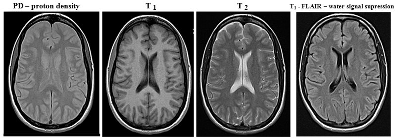
Fig.3.4.5 MRI images of the brain (transaxial
section, without pathology) in proton density, relaxation times T
1 and T 2 and in a special FLAIR sequence
to suppress the water signal.
(MRI brain images were taken by Jaroslav
Havelka, MD, head of the MRI RDG department at the University
Hospital Ostrava )
Proton densities and especially
relaxation times are different not only for
different types of tissues (see table above), but also differ
depending on the physiological or pathological condition of the
same tissue. This makes NMRI imaging an important diagnostic
method in medicine, including in the field of tumor
diagnostics.
Note:
As with X-ray diagnostics, NMRI also uses contrast agents
to increase the contrast of images of certain structures (eg
cavities or blood vessels), but not on a density but on a
magnetic basis - ferromagnetic compounds, mostly
based on gadolinium . Pulse sequence in NMRI
In medical MR imaging, it is desirable to create images with
sufficient high contrast between different
tissue types so that the MRI radiologist can best answer the
clinical diagnostic question. Optimal image contrast between
different tissues with different densities and rexation times can
be achieved by suitable excitation of magnetic moments of nuclei
and subsequent measurement of their response MR signal:
by setting parameters of pulse sequence - time
sequence of transmitted electromagnetic excitation pulses RF and
subsequent measurements of the "echo" of the
electromagnetic signal emitted by the relaxing nuclei. The first parameter here is the intensity
(energy) of the transmitted radio frequency excitation pulse (RF),
which determines the predominant angle of deflection (tilt) of
the magnetization vector of the analyzed nuclei - 90° or 180°.
The higher the excitation intensity radiated into the analyzed
target tissue, the higher the percentage of reversal of the
magnetic moment of the nuclei and the stronger the response
signal and more time is required for relaxation. Another
parameter is the time interval TR , in which we repeatedly
apply individual radiofrequency excitation pulses. The shorter
this interval, the less time there is for T1 relaxation. The
third parameter is the time TE (echo time) between the excitation
pulse and the detection of the response resonant signal. The
longer this time, the less nuclei with a shorter relaxation time
T2 will contribute to the measured resonant signal. The
completely approximate values of the pulse sequence times for
obtaining the basic types of MRI images at B = 1.5 T are :
PD: TR
= 1000 ms, TE = 5-30 ms; T 1
-weighted: TR = 10 ms, TE = 5-30 ms; T 2 -weighted: TR = 1000-2000 ms,
TE = 80-100 ms.
In connection
with these regularities, several significant sequences
of transmission of excitation radiofrequency pulses and
subsequent detection of response relaxation signals have been
developed (sometimes called "MRI
techniques" in MR jargon ) :
-> Saturation - recovery sequence in which
90° RF pulses are transmitted at regular intervals. Upon arrival
of each RF pulse, the magnetization vector rotates 90° and
relaxation begins with different times T1 in different tissues. When another RF pulse arrives, the
z-component of the magnetization will be different in different
tissues. With a suitable repetition period TR of excitation RF
pulses, we can set the optimal contrast of the desired tissues at
times T1 . This
simplest MRI technique is now rarely used, it has been replaced
by the inversion-recovery sequence below, providing
higher contrast.
-> Spin - echo sequence consisting of a
90° RF pulse followed by a 180° RF pulse. After the
magnetization vector has been flipped into the xy plane due to a
90 ° RF pulse, T 2 (resp.
T2 *) relaxes, during
which phasing occurs. However, the subsequent 180° RF pulse has
a "refocusing" effect - it flips the individual spins
in the xy plane by 180 ° and the spins are phased again. The
result is an echo signal in the receiving coil, the amplitude of
which depends on the relaxation times T 1 and T 2 of
the tissue (unfavorable T2 * does not apply here, because the
effect of magnetic field inhomogeneity on phasing is eliminated
by 180 ° pulse phasing) . The character
and contrast of the display can be adjusted using the times TR
and TE. With short TR and short TE we get T 1-weighted image, long TR and short TE provide a proton
density image, long TR and long TE provide a T 2 -weighted image. Due to this
variability of imaging options, spin-echo is the most
commonly used MRI technique.
-> Inversion - recovery sequence,
consisting of a sequence of 180 ° and the following 90 ° RF
pulse. The initial 180 ° pulse inverts the
magnetization vector to the opposite, after which T 1 relaxation takes place . With a
time interval TI - inversion time , a
90 ° RF pulse then follows, which flips the magnetization vector
into the xy plane. A RF signal dependent on T 1 is detected in the receiving
coilrelaxation time of the displayed tissue. The contrast of the
image can be adjusted appropriately using the TI time. A
significantly more contrasting image can be achieved than with
the saturation recovery technique.
By a special setting of the time T1 = T 1 .ln2, the suppression of the image of
the tissue having this relaxation time T 1 is achieved . By setting the short inversion time TI
(approx. 140ms with a 1.5T magnet) - the so-called short
time inversion recovery STIR - the suppression
of the fat signal is achieved in the image . Conversely,
by extending the time TI (to about 2600ms) - fluid
attenuation inversion recovery FLAIR - we can achieve suppression
of the water signal. Other fine details and anomalies in
the structure of the examined tissues can then be better assessed
on such "cleaned" images.
-> Gradient - echo sequence begins with a
90 ° RF pulse (which tilts the magnetization vector to the xy
plane), after which a magnetic field gradient is applied. The
nuclei in adjacent atoms will thus show a precession with a
slightly different Larmor frequency, which will cause spin
phasing. The application of the second mag. gradient with the
opposite sign, which rephases the spins and at this point the
echo is measured. Used to obtain a T 2 -weighted image.
->
..........
sequence ............ ? add more sequences? ........... ?
complete the picture of the graphic sequence diagram? ...
Computer analysis of MRI
images obtained with appropriate sequences (mentioned
above) can create special image
modulations - such as water or fat signal suppression images
. Other special sequences are used for functional
MRI (mentioned below) :
->
Susceptibility weighted imaging ( SWI
) shows tissues with slightly different magnetic susceptibility.
It uses an extended gradient-echo sequence for display in T 2 * . Its
main variant is Blood oxygenation level dependent
(BOLD) , see fMRI
below .
->
Diffusion weighted imaging (DWI) shows the diffusion of water inside tissue
elements, manifested by Brownian motion of molecules. Using a
spin-echo sequence with the application of 2 gradients, a subtle
effect is registered, in which Brownian-moving water molecules
show a different phasing-phasing relationship when reversing the
mag. gradient; this leads to a slightly weaker T 2 signal.
MRI Magnetic Resonance
Spectrometry MRI
Magnetic resonance imaging (MRS) can be supplemented by the magnetic
resonance spectrometry (MRS) described above, which
enriches this examination with additional physiological
information . Chemical analysis is
performed here by analyzing the chemical shift
of the Larmor frequency imaging structures in-vivo, eg choline or
lipid levels. Chemical shifts are very fine, so this method is
demanding not only in terms of signal analysis, but also requires
high intensity (recommended at least 3 T) and homogeneity of the
magnetic field.
Functional magnetic
resonance imaging - fMRI
Magnetic resonance imaging may be a suitable method for
non-invasive imaging of the function of various
tissues and organs (along with "molecular" imaging in
nuclear medicine - .....). So far, fMRI has found application
mainly in functional brain imaging, mapping neuronal
activity . Neurons (which do not
have internal energy stores) they need to
get sugar and oxygen quickly for their increased activity. The
hemodynamic response to this need causes an increase in blood
perfusion at a given site, but mainly a greater release of oxygen
from the blood than inactive neurons. This leads to a change in
the relative levels of oxygenated oxyhemoglobin and
non-oxygenated deoxyhemoglobin in the blood at sites of neuronal
activity.
In this respect, two basic
methods of indirect mapping of neuronal activity are used :
-
Local increase of perfusion
at the site of increased neuronal activity - perfusion fMRI
.
-
Change in the ratio
of oxygenated and non-oxygenated blood at the site of
neuronal activity. The method is called BOLD fMRI
(Blood Oxygen Level Dependent). Changes
in the relative levels of oxy- and deoxy-hemoglobin can be
detected based on their slightly different magnetic
susceptibility. Basic hemoglobin without bound oxygen
(deoxyhemoglobin) has slightly paramagnetic properties,
but when oxygen is bound to it (oxyhemoglobin), it behaves
slightly diamagnetically. If more deoxyhemoglobin
accumulates at a certain site in the brain tissue, a slightly
stronger MRI signal is obtained from it than from the sites where
deoxyhemoglobin predominates.
MRI functional imaging of the brain is
performed after neurological activation, either
motor (eg movement of fingers) , visual, linguistic or cognitive.
The
physical-electronic implementation of NMRI
NMR imaging isthe most complex imaging
method. The operation of the device for NMR imaging is
electronically very complicated and demanding, so it must be
controlled by a powerful computer with
sophisticated software - Fig.3.4.4d. In the multiplex
mode, the process of transmitting a sequence of radio
frequency pulses, modulation of gradient magnetic fields, sensing
and analysis of relaxation signals of magnetic resonance,
reconstruction and creation of the resulting images, as well as a
number of other transformation and correction procedures are
synchronously controlled. Since these are harmonic (sinusoidal)
waveforms, scanning and reconstruction are performed using Fourier
analysis - in the frequency so-called K-space.
It is a set of matrices defined in the memory of the MRI
evaluation computer, into the individual elements of which the
frequencies, amplitudes and coordinates of MRI signals are
recorded. From these "raw" data, the resulting MRI
images are created using Fourier transform and other
analytical methods.
Note:
Electron paramagnetic resonance (EPR) is based on a
similar principle as NMR . The magnetic moments of the electron
shells of atoms are used here .........
3.5.
Radioisotope tracking methods
Radioisotope tracking or indicator
methods are used to monitor the hidden movement and distribution
of matter within physical, chemical or biological systems, or in
various technological devices. A suitable "labeled"
substance with bound radionuclide is introduced into the system -
the so-called radioindicator, whose movement and
behavior in the system is then monitored on the basis of
detection of ionizing radiation emitted during radioactive
transformations of nuclei in the radioindicator. The movement and
distribution of the radio indicator can be monitored in two basic
ways :
- Sampling from suitable
places of the monitored system, their adjustment and
measurement with a suitable detector (g or b).
- External detection of
emitting radiation radiation g by detector
placed in suitable places of the examined system
(occasionally inside, mostly outside the monitored
system).
Radioisotope tracking methods are used in many
fields of science and technology, industry, agriculture and
especially medicine. Here we will briefly mention a few technical
and general biological applications, we will focus in more detail
below on applications in nuclear medicine.
Radioisotope
tracking methods were first tested in 1913 by the
chemist G.Hevesy, who found that radioisotopes have the same
chemical behavior as stable isotopes of the same
element. However, unlike stable isotopes, radionuclides can be
"visible" through the penetrating radiation
generated by the transformation of nuclei.
Radioisotope
scintigraphy and nuclear medicine
Nuclear medicine is a field dealing with diagnostics
and therapy using radioactive substances
in open form, applied to the internal environment of the
organism.
Radioactive isotopes react chemically
in the same way as stable isotopes of the same element -
therefore they behave in the organism's metabolism in the same
way as non-radioactive isotopes of a given element. However, due
to the fact that radioactive isotopes are "visible"
through penetrating radiation, which arises during radioactive
transformations of their nuclei, it is possible to monitor
the movement and metabolism of elements and compounds
containing radionuclides - radioindicators - in
the body and thus investigate the functions of
individual organs. Depending on the organ whose function is to be
examined, the specific substance (radiopharmaceutical)
shall be labeled with an appropriate radioisotope. After
application to the body, the movement and metabolism of this
substance is monitored - mainly imaging with a gamma
camera, possibly supplemented by measurement of samples
(blood or urine).
Radioisotope
diagnostics in vivo - scintigraphy
In radionuclide diagnostics in vivo in nuclear medicine,
the patient is administered (usually intravenously, sometimes
orally or by inhalation) a small amount of a suitable g -
radioactive substance - the so-called radioindicator
or radiopharmaceuticals. The radioindicator used is specific
to individual organs and types of examinations. The applied
radioactive substance enters the metabolism of
the organism and is distributed there according to its
chemical composition - physiologically or pathologically it accumulates
in certain organs and their parts and is subsequently excreted or
regrouped. Gamma radiation emanates from the deposition
sites of the radioindicator, which, due to its penetration,
passes through the tissue out of the organism. Using sensitive
detectors, we measure this radiation g and thus determine the
distribution of the radioindicator in individual organs and
structures inside the body.
The most perfect devices of
this kind are gamma cameras (scintillation cameras) -
using them we display in radiation g the distribution of the
radioindicator in the organism. This method, called scintigraphy,
thus makes it possible to obtain not only anatomical information,
but mainly to tell about organ functions and metabolism. By
mathematical evaluation of scintigraphic images, we can obtain
curves of the time course of the radioindicator distribution and
calculate dynamic parameters characterizing the function
of the relevant organs.
Schematic arrangement of the entire process
of scintigraphic examination - from the application of a
radioindicator to the patient, through the process of
scintigraphic imaging with a gamma camera, evaluation,
mathematical analysis and quantification, to the interpretation
and determination of diagnosis.
The tomographic gamma camera
SPECT (Single Photon Emission Copied Computerized
Tomography) slowly rotates around the
patient's body, scans scintigraphic images from various angles
and then uses computer reconstruction to create cross-sectional
images (sections perpendicular to the camera's axis of
rotation), from which computer graphics can be used to construct spatial
(3-dimensional) images of the distribution of the radio-indicator
in the organs inside the body.
The PET gamma camera
(Positron Computerized Tomography) detects photons of
gamma annihilation radiation (511 keV energy)
flying in opposite directions during the annihilation of
positrons, emitted by b+ radioindicator
administered to the patient. These photons of annihilation
radiation are coincidentally detected by an
annular scintillation detectors, and by computer reconstruction
of the line projections of the coincidence sites, images of
cross-sections are generated and, if necessary, 3D images similar
to SPECT.
Nuclear medicine provides
specific methods for the examination of virtually all organs and
thus cooperates with a wide range of clinical disciplines. The
most widespread use is mainly in cardiology, nephrology,
neurology, oncology, thyrology, gastroenterology.
Nuclear medicine methods are
among the least burdensome non-invasive diagnostic
examination methods. Due to the high sensitivity of the
detectors, only a very small amount of radiopharmaceutical is
applied to the patient, which is needed to obtain quality image
information. The radiation exposure in methods in nuclear
medicine is comparable (and often smaller) as in X-ray
examinations *).
*) During X-ray examination, the source of
ionizing radiation is a device (X-ray tube) and the radiation
dose depends, among other things, on the number of images
performed, or on the extent of the area scanned during CT. In
scintigraphy, the source of radiation is not a diagnostic device,
but the patient himself, resp. its investigating body. Thus, we
can take any number of scintigraphic images without changing the
radiation exposure of the patient.
Radionuclide scintigraphy is described in detail in
Chapter 4 "Radioisotope
scintigraphy".
Radiation-guided surgery - sentinel nodes
An important radioisotope tracking method of nuclear medicine is
local radiation measurement with a closely collimated miniature
gamma-ray detection probe in radiation-guided surgery in the
detection of so-called sentinel nodes.
In the surgical treatment of cancer, it is important to remove
not only the primary tumor, but also, if possible, other tissues
into which the tumor cells could be infiltrated. These tumor
cells spread from the primary site mainly through the lymphatic
pathways, so that the lymph nodes around the
tumor site are the first to be affected. If we apply a suitable
radioindicator of colloidal state to the peripheral part of the
tumor lesion (most often 99mTc nanocolloid, particle size approx. 50-600 nm,
activity approx. 40-150 MBq), it will propagate through the
lymphatic pathways and capture and accumulate in
those nodes, that are lymphatically associated with the tumor
site. The first such node in the lymphatic "watershed"
of a tumor foci is called the sentinel node. The
accumulation of the radioindicator in the nodes can be displayed
scintigraphically. However, the most important thing is to
monitor the radioindicator during the actual surgical procedure,
when using a collimated detection probe, the surgeon can find a
sentinel node containing the radioindicator directly in the
operating field.
*) Along with the radioindicator, a blue
dye is applied at the same time, which also penetrates the nodes,
so that the surgeon can recognize the sentinel node also by its
blue coloration.
After application of the
radioindicator, scintigraphic imaging is performed with the
displayed nodes marking, then the patient goes to his own surgery,
during which a detection gamma probe is used both for
perioperative sentinel node detection and for radioactivity
detection in an already operated node. This is followed by
histological examination of the sentinel node to classify the
type of tumor, which will help optimize the further course of
therapy. ......"...."......
In vitro diagnostics. Radioimmunoassay
- radiosaturation analysis
In nuclear medicine, in vitro radioisotope diagnostic methods
are also used, where (non-radioactive) samples taken from
patients are analyzed using radioisotope
techniques - radiochemical and at the same time biochemical. Most
often it is a radioimmunoassay (RIA) or radiosaturation
analysis (RSA), which is used to highly sensitively
determine the concentration of complex biological substances in
the blood serum - hormones, tumor markers and other biologically
important substances. It is based on an immunochemical reaction
antigen with a specific antibody (Ab - antibody). A competitive
immunoreaction is used in which the radiolabeled Ag* antigen
"competes" for binding sites on the antibody (which is
present in a limited amount in the reaction mixture) with the
unlabeled antigen. An appropriate antibody labeled with
the appropriate radionuclide Ag*
(usually I-125-radioiodine) is
added to the sample analyzed, which reacts with given hormone to
form an insoluble Ag*-Ab complex. After removal of the unbound
fraction (rinsing with water), a compound remains in the sample,
the activity of which will depend on the concentration of hormone
in the analyzed sample - the amount of labeled antigen-antibody
Ag* -Ab complex is inversely proportional to the concentration of
antigen to be determined. The more test substance present in the
primary sample, the smaller the amount of labeled Ag* -Ab
antigen-antibody complex formed and the lower the activity in the
final sample. It is measured in a well scintillation detector (see §2.7, section "Automatic
measurement of a series of samples") . These methods are of
great importance for endocrinology.
RIA or RSA methods reached their greatest
development in the 1970s and 1980s, when they were widely
performed in radiochemical RIA laboratories at
the departments of nuclear medicine. Then they
gradually moved from nuclear medicine workplaces to clinical
biochemistry laboratories. Since the 1990s, they have
been gradually extruded and replaced by fluorescent and
chemiluminescent optical methods, without the use of
radionuclides and ionizing radiation...
Radioisotope
therapy
In addition to diagnostics, nuclear medicine also includes therapy
with open radionuclides, eg treatment of hyperthyroidism and
thyroid cancer, blood diseases, palliative and curative therapy
for various types of tumors, joint diseases - see below for more
details in §3.6 "Radiotherapy", part "Radioisotope therapy".
Nuclear medicine -
interdisciplinary field
Nuclear medicine, due to the physical nature of its methods
and instrumentation used, is an interdisciplinary field.
Besides doctors (specialist and
certified in the field of nuclear medicine),
nurses and laboratory technicians, are working in team work
as well as experts from other professions - physicist, electronics,
radiochemicist, pharmacist. Along with medical and
physical-technical aspects, considerable attention is also paid
to radiation protection of workers and patients in the
workplaces of nuclear medicine when working with radioisotopes (see Chapter 5 "Biological
effects of ionizing radiation. Radiation protection").
A detailed description of the
principles, methods and clinical use of nuclear medicine is in
Chapter 4
" Radionuclide scintigraphy " .
Autoradiography
- photographic imaging of the distribution of
the beta-radioindicator in the examined preparations in close
contact of the photographic emulsion with sample is
described in §2.2 "Photographic detection of ionizing
radiation", passage "Autoradiography".
3.6.
Radiotherapy
Radiotherapy is a physico-medical field using the biological
effects of ionizing radiation for therapeutic purposes.
The vast majority of it is a therapy of tumor diseases, cancer
- radiation oncology, to a lesser extent, some
degenerative and inflammatory disorders are treated with
radiation. Recently, so-called radiosurgery has
sometimes been used, especially for vascular and neurological
malformations (see the "Stereotactic radiotherapy"
section). Before we focus on our own
radiotherapy, we will mention some biological aspects of cancer,
diagnostics and non-radiation therapeutic methods (chemotherapy,
biological therapy) - to put the issue in a broader context.
Tumors
- their nature and origin
Higher organisms, including us humans, consist of billions of
cells of various types and functions in a variety of tissues and
organs. These cells have a limited lifespan, they disappear after
a certain period of time (mostly by
apoptosis - §5.2, passage "Mechanisms
of cell death"), while they are mostly replaced by new cells, created
by the division of existing cells. The process of cell
death and division is under normal circumstances rigorously
controlled to ensure tissue homeostasis. During their
lifetime, cells are often exposed to various harmful influences
from both the outside and the inside. The resulting small damages
are mostly repaired by intracellular repair mechanisms, and the
cells repaired in this way can then perform their original
functions again (see §5.2, passage "Repair
processes"). In case of severe damage, the cell usually dies.
However, it can sometimes happen that "moderate" damage
is not fatal for the cell, nor can it be repaired flawlessly;
such a cell can continue to divide, but with disturbed genetic
information in the DNA - with a mutation. This, under
certain circumstances, can lead to a violation of the control of
the process of cell division and ultimately result in the
pathological uncontrolled multiplication of cells - the
emergence of cancer.
Tumors,
especially malignant, are among the most common and most serious
diseases, threatening the health and lives of patients. During
the formation of a tumor, pathological tissue mass (neoplasm)
is formed, usually irreversible, in which uncontrolled
proliferation of tumor cells takes place,
at the expense of healthy tissue; there is no feedback in the
body to stop this growth. Tumor cells can grow into the
surrounding tissue and migrate through lymphatic or blood vessels
to other parts of the body (establish metastases). With
its uncontrolled division of the mass of tumor cells, it
suppresses the surrounding healthy tissue, disrupts it and can
thus violate the function of important organs. The cause of such
a condition it is not exactly known *), it lies deep inside the cell
structure, probably in mutational changes in DNA.
Prevention and causal treatment of tumor diseases - cancer
- is therefore difficult.
*) Only some risk factors were
observed, which contribute to the formation of tumors or increase
the probability of their occurrence. They are various chemical
substances, so-called carcinogens, such
as some cyclic hydrocarbons and cigarette smoke, the composition
of food. Or biological effects - some viruses (so-called oncoviruses
), whose RNA can (via so-called reverse transcriptase)
enter the DNA of eukaryotic cells and alter their genetic
information, they can cause tumor transformation of cells (or
they may not lead directly to tumor formation, but prevent an
immune response that would be able to recognize tumor cells and
destroy them). Then there are genetic
factors , hereditary predisposition (hereditary genomic
imprinting eg in Nyemegen syndrome, Ataxia teleagiectasia,
Bloom's syndrome, Fanconi anemia, Xeroderma pigmentosum,
Li-Fraumeni syndrome of the mutated TP53 gene encoding p53); it
is caused by a specific mutation in the tumor suppressor
genes (TP53 gene mutation in Li-Fraumeni syndrome, NF1,2 in
neurofibromatosis, BRCA1,2 in hereditary breast and ovarian
cancer, APC in colorectal polyposis, WT1 and Wilms' kidney tumor,
RB1 in retinoblastoma, MLM gene mutation in malignant melanoma).
Of the physical influences, it is ultraviolet radiation
acting on the skin and especially harder ionizing
radiation, as discussed in detail in §5.2 "Biological effects of ionizing radiation".
Is cancer a new
civilizational disease (which did not occur in the past) ?
This opinion is often found among people, but it is wrong.
Cancerous diseases undoubtedly began to appear immediately after
the emergence of multicellular more complex organisms with
specialized cells for different functions. Even then, some cells
with unrepaired genetic damage in their DNA "forgot"
what function they should perform in the organism and could begin
to multiply uncontrollably.
Most cancers affect soft tissues, so their
remains cannot be found in paleontological and archaeological
findings. Only bone tumors leave distinct fossil traces. It was
possible to find a sample of turtle bone approximately 240
million years old, destroyed by bone cancer. In human ancestors,
tumor destruction of bone was found in an approximately 2 million
year old Australopithecus bone. In historical times, cancer was
already described in ancient Egypt. However, until the 19th
century cancer was considered relatively rare. People then
suffered and died from many other diseases. Today we are able to
cure most of them (some have been
practically eradicated). But tumor
diseases, especially at a more advanced stage, are still
difficult to treat even now.
The increased incidence of cancer in
recent times is due to more perfect diagnostics, but probably
unfortunately also to the worse lifestyle of
most people in a consumer society.
Carcinogenesis
- the formation of tumors
Under normal circumstances, a multicellular organism is a system
of individual tissues and organs, consisting of a large number of
cells, performing their function in a harmonious community for
the benefit of the whole organism. This cooperation and
"social behavior" of cells is ensured by very intricate
and complex regulatory processes, including signals from
monitoring the external environment, transmission of signals to
the internal environment of the cell, cellular response,
evaluation of signals and their coordination with other signals.
Cells that do not fit into this regulatory mechanism (due to
damage or loss of their function) are eliminated by the
mechanisms of "programmed" cell death, apoptosis.
Also, cell proliferation is precisely controlled to meet the
needs of the tissue and the organism - dynamic balance, tissue homeostasis.
Disruption of regulatory mechanisms can cause various
pathological conditions and diseases of the body. One of them is
a violation of the regulation of cell division: in some cell a
genetic change (mutation) occurs that allows it to survive,
divide and produce daughter cells that do not "listen"
to the regulatory mechanisms of tissue homeostasis. This can
create a gradually expanding population of mutated cells - a
clone of tumor cells, multiplying at the expense
of healthy tissue.
Tumor formation (carcinogenesis) is a complex
multi-step process in which several mutations gradually
accumulate, which do not harm the altered cells, but on the
contrary favor them and allow their rapid division regardless of
the needs of the organism. The following factors are important
for the origin and development of cancer :
->
Cell cycle
deregulation
To maintain tissue homeostasis (a balanced number of
functional cells of a given tissue) it is necessary to control
the rate at which cells form, develop and die - cell
cycle regulation. Due to some mutations, autonomic
growth (mitogenic) factors in the cell, their autocrine
production, or loss of sensitivity to signals that stop the cell
cycle may occur. In particular, p21 and p27
proteins are involved in cell cycle regulation and division,
which may bind to and inhibit the activity of certain kinases
(serving as regulators of DNA replication and cell division); the
content of these regulatory proteins in tumor cells tends to be
reduced. On the contrary, the activity of some kinases (§5.2, section "Cells
- basic units of living organisms",
passage "Proteins, enzymes, kinases")
is increased in tumor cells. It is mainly a
tyrosine kinase - an enzyme which transfers
phosphate to the hydroxyl group of the cyclic amino acid
tyrosine, thereby affecting the function and activity of the
respective protein. Increased epidermal growth factor receptor
(EGFR) tyrosine kinase activity leads to
increased intracellular signaling, disrupting cell cycle
regulation. This increased EGFR activity may be due to increased
expression of the EGFR ligand (which is the epidermal growth
factor EGF), or by a mutation in the EGFR tyrosine kinase domain
that results in sustained ligand-independent activation of the
mutated receptor. Another receptor which promotes cell growth and
division, the epidermal growth factor receptor HER2 (Human Epidermal Receptor), also called erbB2, in the increased presence
of which there is an excessive division of cells, which can lead
to the formation of a tumor. Also, deregulated signal
transduction through the P3K / Akt / mTOR
phosphatidylinositol-3-kinase signaling pathway provides
cells with stimuli for unrestricted growth and survival, which
can lead to tumor growth.
Disruption of cell cycle
regulation can lead to the proliferation of such altered cells
independently of the environment, independent of the needs of the
tissue and the organism - it is usually the first stage
of carcinogenesis.
->
Inhibition of
apoptosis
Another important mechanism for maintaining tissue homeostasis is
the regulation of the rate at which "excess" cells in
the tissue population die. The usual way in which cells undergo
controlled death is apoptosis (described in more detail in §5.2, section "Effect
of radiation on cells", passage "Mechanisms
of cell death", where the
internal and external signaling pathways of apoptosis are
discussed) - "programmed" cell
death, actively controlled by the cell . The apoptotic
program is potentially present in all cells, it is triggered by
internal signals (DNA damage, hypoxia, ...) or external
"death signals" that the cell receives from regulatory
mechanisms in the tissue. Properly functioning apoptosis,
triggered by external regulatory mechanisms from the tissue,
provides effective protection against excessive cell
proliferation. Apoptosis triggered by internal mechanisms then
acts as a protection against the survival and proliferation of
mutated cells with damaged DNA. Inhibition (blockage, damage) of
apoptosis - apoptic resistance of cells - allows developing tumor
cells to survive and multiply, despite the organism's interest.
Apoptosis can be disrupted, for example, by altering the TP53
gene encoding the p53 protein, increasing the concentration of
the anti-apoptotic Bcl-2 gene in mitochondria (protecting mitochondrial membranes - preventing cytochrome
c penetration and caspase chain triggering proteolytic
degradation in the cytoplasm) and other
unexplored factors.
Note: This is
mainly a suppressed apoptosis induced by external
regulatory mechanisms of the tissue. However, with strong
irradiation of tumor cells, which causes severe irreversible DNA
damage, internally activated apoptosis occurs .
->
Immortilization
of cells
Most common somatic cells can only reach a certain limit
in the number of their divisions, the so-called Hayflick
limit (about 40-60 cycles); then the cells lose their
ability to divide. This is due to mitotic
shortening of DNA telomeres (about cell cycle, telomere
shortening, cell senescence, apoptosis, etc. see also §5.2
"Biological effects of ionizing radiation"). This limit in the number of divisions
would automatically stop the growth of the tumor population.
Increased occurrence of an active enzyme called telomerase
(in co-production with tankyrase), or mechanisms of
homologous recombination of telomere sequences (discussed in
§5.2, part "DNA,
chromosomes, telomeres"), however, they are able to
ensure complete replication of DNA ends (prevent telomere
shortening) - gaining unlimited
replication potential, so-called immortilization
-"immortality"of cells. Unregulated and unrestricted
division of clonogenic tumor cells, which break free from
the mechanisms of tissue homeostasis, is a typical feature of
tumor diseases.
->
Inhibition of
immunogenity
The immune system is fundamentally capable to recognize tumor
cells and destroy them. Some tumor cells, however, they lose
their immunogenicity *) or the immune system is impaired - these
cells are outside the control of the immune mechanisms and may
cause their uncontrolled proliferation.
*) Many tumor cells have the CD47
protein on their surface, which protects them from white blood
cells (physiologically, this protein occurs on the surface of
blood cells to protect them from its own white blood cells) and
therefore cannot be destroyed by the immune system.
->
(neo)Angiogenesis
In the initial stages (tumor size up to about 0.5-1 mm), tumor
cells are supplied with oxygen and nutrients by diffusion from
the surrounding intercellular environment of the tissue in which
the tumor grows. As the number of tumor cells increases, this
supply is no longer sufficient - there is hypoxia
of the tumor tissue, accompanied by the expression of special interleukins,
especially HIF1 (hypoxia-iducible transcription factor),
inducing the production of vascular endothelial growth factor
VEGF (as well as VEGF mRNA expression). The regulatory
mechanisms in the tissue can respond to this by angiogenesis
- the formation of new blood vessels, ensuring the blood supply
to the tumor tissue and its rich supply of oxygen and nutrients,
as well as flushing out metabolic waste. Tumor growth is
dependent on angiogenesis - it necessarily requires a sufficient
supply of nutrients and oxygen, which are provided by newly
formed blood vessels. Each increase in tumor volume is associated
with the growth of new capillaries.
Tumor neo-angiogenesis
or neovascularization is an important
milestone in the progression of cancer, allowing tumors to grow
to macroscopic size, threatening tissue and whole
organism. Blood flow to the tumor tissue also allows the spread
of tumor cells through the bloodstream - the formation of metastases
:
-> Formation of metastases
In most cancers, the most
dangerous feature of tumors is the ability to create secondary
foci, so-called metastases (Greek: meta=change, stasis=place -> change of place,
relocation). Metastases are the cause of
more than 90% of cancer deaths. Tumor cells can grow into the
surrounding tissue, separate from the original tumor and migrate
to other parts of the body through the lymphatic or blood paths,
settle there and create secondary foci - establish metastases.
The tumor cell first penetrates into the surrounding tissue and
then into the blood or lymphatic stream. If it survives in this
watershed, it can be carried by it and migrate to other tissues
and organs. There it can leave this riverbed and penetrate the
tissue in a new place, establish itself there and begin to
divide. Metastasis is often a chain: from the secondary
metastasis, tumor cells are released and migrate and establish
other, tertiary, metastases, etc. The result can be the spread of
cancer throughout the whole body - generalization.
The issue of carcenogenesis is very complex, with a
number of unexplored factors. In addition to mutations of known
and coding genes in DNA, so-called "genetic litter"
or "unnecessary DNA" sequences can also may
manifest, which via the respective RNA can function as regulatory
"triggers" or "switches" of intracellular
processes (see also §5.2, part "DNA,
chromosomes, telomeres") .
So to
sum it up briefly, cancer occurs when some (originally
healthy and functional) cells in the body
undergo several mutations in their DNA and begin to divide
uncontrollably, and at the same time the body's immune
mechanisms unable to stop this growth. The occurrence of cancer
is a stochastic phenomenon, it is not possible to
specifically predict if and when it will occur in a given
individual; the probability of its occurrence can only
be estimated statistically.
Dependence on the
age and size of the organism ?
The mechanisms of carcinogenesis and the stochastic occurrence of
cancer lead to the expectation that the more cells an organism
has in its body and the longer it lives, the greater the risk of
developing cancer. The time factor of the growth of cancer risk
with the age of a specific individual is indeed almost always
applied - the longer someone lives, the more time their cells
have to mutate; and at the same time the immune processes also
weaken during aging. In dependence on the size of the organism,
however, the situation is more complicated. Some large and
long-lived animals hardly suffer from cancer, even though they
have many more cells and live as long or even longer than humans.
They are, for example, bowhead whales, elephants, but also cows
and horses. On the other hand, some small animals such as mice
and rats, with a relatively short life of about 4 years, are
highly susceptible to tumors. One of the factors behind this is faster
metabolism (-> formation of a larger amount of mutagenic metabolic
products) and faster cell division (-> more frequent
mitotic reproduction of potential errors in DNA). In large and
long-lived animals, which usually also have a slower metabolism,
also genetic factors were found, consisting of an
increase in the TP53 gene, which codes for the p53 protein that
triggers apoptosis, or in general a faster development of
tumor-suppressing genes. There is a vague hope, that some of
these molecular-genetic anti-tumor strategies will be
artificially applied in clinical oncology in the future ..?..
Types of tumors
Tumors and tumors disease (lat. tumor =
swelling, edema), often collectively
referred to as carcinoma or cancer, are
characterized by a large number of species and great variability.
They are divided according to several criteria :
l According to health severity :
× Benign tumors (lat. Benignus = harmless, friendly, generous )
are usually localized and isolated from the
surrounding tissue by encapsulation, do not grow into other
tissues and do not form distant metastases. They do not have to
create major damage or difficulties for the organism (they can
often remain in the tissue - but beware of the risk of malignant
degeneration!), if necessary, they can usually be successfully
surgically removed.
× Malignant tumors (lat.
malignus = evil, evil-bearing ),
grow destructively and infiltratively - tumor
cells grow into the intercellular spaces of the surrounding
tissues (which suppress and disrupt), the cells are released and
spreads through the blood or lymphatic route to other tissues and
organs, where they often form distant secondary "daughter
deposits", so-called metastases (Greek meta = change, stasis = place ® change of
place, relocation). Even after removal
of the primary tumor site, metastases can continue to grow and
form more metastases. Due to metastatic spread (dissemination)
can lead to the uncontrolled spread of the disease, often to the
whole organism (generalization).
l According to the organ from which the
tumor primarily originates : - eg breast,
lung, bronchogenic, prostate, etc.
l By name of cells and tissues. The name
of the tumor is formed from the Latin name of the tissue, organ
or original cells from which the tumor arose and the ending "-oma"
is added to this name - e.g. melanoma or melanoblastoma
(skin tumor of melanocyte cell ), glioma or glioblastoma
(primary brain tumor, also astrocytoma ), lymphoma
(tumor growth of lymphoreticular tissue), etc. A malignant tumor
of hematopoietic tissue, manifested by an increase in white blood
cells (which are immature and do not perform their normal
function), is called leukemia .
l According to the location of metastatic
involvement - eg metastasis of breast cancer to the
liver, skeleton, etc.
l By tissue and cell nature :
- Epithelial tumors
called (in the narrower sense) carcinomas are the most
common type of cancer. According to the cell layer from which
they originate, they are further divided into squamous cell
and basal cell carcinomas (these names come from skin
tumors).
According to the microscopic appearance of cancer cells (for
histologic observation) and shape of the tumor growth is
sometimes used designation papillary (warty - tumor
forming warty or fimbriate formations), tubular (forming
a tubular structure), medullary (marrow), ductal
(outlet pipe), lobular (lobe ) and the like.
Benign tumors arising from the glandular epithelium are called adenomas
.
- Mesenchymal tumors , called sarcomas,
come from connective tissues. They occur less often.
The resulting terminology of specific types of tumors is
often formed by combining the names of individual categories - eg
prostate adenocarcinoma, osteosarcoma in the
skeleton, etc.
Some particular species of
tumors
Tumor diseases are very diverse, about 100 types and subtypes of
tumor diagnoses have been described. Here we briefly mention
several more well-known and more frequently occurring types of
cancer :
-> Skin
tumors primarily affect the skin, but they can grow into
deeper layers of tissue, some types even establish metastases. Malignant
melanoma is a cancer that arises from the neoplastic
proliferation of melanocytes. A risk factor is UV radiation (including excessive tanning in the sun). Melanoma initially spreads radially in the skin, later
it can metastasize to lymph nodes or hematogenously to internal
organs. In this case, it is very dangerous, it is one of the most
malignant tumors! Basaliom - basal cell skin
cancer - develops in the basal cell layer of the skin. It is the
most common cancer of the skin. UV radiation also contributes to
its formation. It is mostly benign and rarely metastasizes. It is
removed by excision or laser. Squamous cell carcinoma
(spinalioma) arises from flat cells of "squamous"
shape, which are found in the epithelial tissue of the middle
layer of the skin. It can later metastasize (mainly
by the lymphatic route), so it should be
removed by excision even with a safety margin. The name squamous cell is also used for squamous tumors
of the lining of hollow body organs, respiratory tract, uterus.
-> Lung
cancer - bronchogenic - is a common disease especially
in men, the main risk factor is smoking. Malignant proliferation
of epithelial tissue cells usually occurs. The two main groups
are small cell and non-small cell lung cancers.
Non-small cell carcinoma is more common. It is divided into
adenocarcinoma (arising in the marginal lung tissue), squamous
cell carcinoma (originating from the epithelium of the large
airways) and large cell carcinoma. Small cell carcinoma is made
up of small cells shaped like oat grains, it soon metastasizes
through blood and lymphatic vessels, and is more difficult to
treat. In addition to primary lung tumors, metastases of
malignant tumors from other tissues (such as breast cancer,
.....) can also occur in the lungs; Circulating tumor cells can
easily become trapped in the capillary blood vessels of the
lungs.
-> Breast
cancer is the most common cancer in women. The most
common (about 80%) is ductal carcinoma of the breast,
which arises from the cells lining the ducts of the mammary
gland. Furthermore, lobular ca of the breast (10-15%)
arising in the lobules of the mammary gland. According to
histology, breast cancers are further divided according to the
presence of tumor markers/receptors on the surface of the cells,
such as HER2+. This is important for biological treatment. In
addition to the lymph nodes (most often in the armpit),
breast tumors often metastasize to the skeleton, liver,
and lungs. For early diagnosis of breast cancer, regular
mammography is recommended after the age of 40 (described above
in §3.2, passage "X-ray mammography").
-> Gynecological
tumors in women - uterus and cervix, ovaries. One of the
risk factors is infection with oncogenic HPV viruses. Cervical
tumors arising from the epithelial layer are most often squamous
cell carcinomas (80%) and adenocarcinomas (20%).
Among uterine tumors, the most common epithelial tumors
are endometrial adenocarcinomas (83%). Ovarian
and fallopian tube tumors are mostly epithelial
carcinomas.
-> Prostate
cancer is one of the most common oncological diseases in
men. Adenocarcinoma of the prostate most often develops
in the peripheral part of the gland. A specific feature of
prostate tumor cells is increased expression of the prostate-specific
antigen PSA. An important diagnostic indication of prostate
cancer is therefore an increased level of PSA in blood
samples (it is also somewhat elevated in
benign hyperplasia and inflammation of the prostate). Advanced prostate cancer can often metastasize to
lymph nodes in the pelvis and to the skeleton. Some prostate
tumors are hormone-dependent, hormonal therapy (castration, estrogens) can be
effective for several years; however, after a longer period of
time, they often become hormonally refractory. Ca prostate tumor
cells have one more specific property that is beneficial for
diagnosis and therapy: in addition to secreting PSA into the
blood, they have an increased occurrence of the transmembrane
receptor Prostate Specific Membrane Antigen PSMA on
their cell wall. Appropriate ligands such as PSMA-617
were developed for this receptor and radioactively labeled both
with diagnostic radionuclides 68Ga or 18F for
scintigraphic imaging, and with therapeutic radionuclides
177Lu or 225Ac for effective biologically targeted
radionuclide therapy. This precise theranostic approach
makes it possible to cure even metastatic hormone-refractory
prostate cancer - see below Prostate
cancer - Radioisotope therapy can win over prostate cancer!".
-> Kidney
and bladder tumors. The most common kidney tumor is adenocarcinoma
of the renal parenchyma, from the epithelium of the renal tubules
(sometimes called Grawitz's tumor). The most common bladder tumors are papillary
tumors arising from the urothelium, which tend to have the
shape of growths protruding into the bladder cavity.
-> Liver
tumors. Primary hepatocellular carcinoma,
arising from malignant degeneration of liver cells of
hepatocytes, occurs relatively rarely. However, the liver is a
frequent site of metastases of various malignant tumors
(cancer of the large intestine, breast, lung, etc.), because
blood flows through it from the digestive tract, which i.a. they
"clean" from metabolites. Circulating tumor cells can
therefore be trapped in the bloodstream of the liver.
-> Colorectal
cancer - colon tumors are mostly adenocarcinomas arising
from the glandular cells of the intestinal mucosa. A risk factor
is polyps - growths from the wall of the intestine, from
which cancer can develop over a long period of time. In the
advanced stage, it often metastasizes mainly to the liver.
-> Pancreatic
cancer arises mainly from the exocrine part of the
pancreas, most often it is an adenocarcinoma from the
epithelium of pancreatic ducts through which pancreatic enzymes
pass. It is initially asymptomatic, usually diagnosed at a late
stage, curative therapy is not yet successful. From the point of
view of endocrinology and biochemistry, pancreatic cancer is
included among the so-called neuroendocrine tumors.
Their specific feature is the presence of somatostatin
receptors, which can be used for biologically targeted
radionuclide therapy using somatostatin analogues labeled with 177Lu
("Neuroendocrine tumors" is mentioned below).
-> Thyroid
cancer can be differentiated (papillary and follicular),
medullary, undifferentiated (anaplastic). Cells of differentiated
thyroid cancer, including possibly metastases, retain the ability
to accumulate iodine, which is the basis of its scintigraphic
diagnosis and mostly successful therapy with radioiodine 131I (it
is described in more detail in §4.9.1 "Thyreological
radioisotope diagnostics" and
below in the section "Biologically targeted radionuclide
therapy", passage "Carcinoma therapy thyroid gland with
radioiodine 131I").
-> Tumors
in the skeleton can be of two origins. Primary
bone tumors originating in cells found in the bones, called bone
sarcomas, such as osteosarcoma, are rare. Bone
metastases are far more common, arising from the malignant
growth of tumor cells originating from tumors of other tissues -
most often of the breast, prostate, uterus and others. Most
skeletal metastases are hematogenous. The vascularized inner
environment of the bone is a "nurture ground" for the
capture and multiplication of tumor cells, which enter the bone
tissue and begin to bind with stromal cells. Osteolytic deposits
in bones caused by multiple myeloma are a special case; this is
not metastasis in the usual sense.
-> Brain
and CNS tumors. Primary brain tumors often arise from
cells of the supporting brain tissue (neuroglia) - gliomas.
The most common are astrocytomas, from less malignant
pilocytic ones to very aggressive and dangerous glioblastomas.
Furthermore, oligodendrogliomas, which are also less aggressive.
In addition to primary brain tumors, the brain tissue is even
more often affected by metastases of tumors from other
tissues and organs (breast cancer, lung cancer, malignant
melanoma, ...), whose hematogenously migrating cells have an
increased probability of being caught, thanks to the high blood
flow to the brain. Intracranial tumors, including metastases, up
to a size of about 3 cm can be relatively successfully treated
with stereotactic radiotherapy (it
is described below under "Stereotactic
radiotherapy"), primarily with the Lexell gamma-knife.
Hemato-oncological tumors -
malignancies of the blood and blood-forming organs - form a
separate specific group of often diffusely localized lesions :
-> Leukemia
is caused by tumor growth of certain types of white blood cells -
leukocytes, which are immature and do not fulfill their
normal function. It is accompanied by the suppression of normal
hematopoiesis. Myeloid leukemia affects the formation of
monocytes or granulocytes, lymphatic leukemia affects the
formation of lymphocytes. Depending on the speed of the course,
leukemia is classified as acute or chronic. The category of myeloproliferative
diseases also includes polycythemia, which is an
increase in erythrocytes in the blood. This increases blood
viscosity, which can impair blood circulation.
-> Lymphomas
form a group of tumors of the lymphatic system, which have
varying degrees of malignancy. They are most often manifested by
enlargement of the lymph nodes ......... According to the type of
tumor cells, they are traditionally divided into Hodgkin
and non-Hodgkin. Monoclonal antibodies such as rituximab
can be used for the therapy of lymphomas, for biologically
targeted radionuclide therapy the monoclonal antibodies
anti-CD37 labeled 90Y ibritutomab tiuxetan or anti-CD20 177Lu-tetulomab
(mentioned below "Immunotherapy of lymphomas").
-> Multiple
myeloma is a malignant disease in which clonal plasma
cells - myeloma plasma cells - multiply in the bone
marrow, which is the seat of hematopoietic cells from which all
types of blood cells arise. Genetic changes occur in myeloma
cells that allow them to grow out of control. Through the
bloodstream (along with normal functional blood cells), they
spread to other places in the bone marrow and sometimes can
infiltrate other tissues as well - multiple lesions often arise.
Tumor myeloma cells produce pathological cytokines, monoclonal
immunoglobulin (also called paraprotein), some of which disrupt
the balance between osteoblastic and osteoclastic activity in the
skeleton. Myeloma lesions often attack the bone tissue from the
inside, creating a number of ostreolytic foci in the affected
bones (they are not bone metastases in the
usual sense). Pathological fractures may
occur in these deposits of decalcification. In addition,
hematopoietic disorders (mainly red blood cells – anemia)
and often kidney damage occur.
An interesting fact is that monoclonal antibodies, which
are important for biologically targeted antitumor therapy and
diagnostics, are obtained from myeloma cells using the so-called
hybridoma technology (described below in the passage "Monoclonal
antibodies").
Anatomical extent -
progression - of tumor disease (staging)
To assess the possibilities of optimal therapy,
the progression of cancer is crucial - how the
tumor growth in the body has spread, how far it has penetrated.
The anatomical extent (progression, staging)
of cancer is often assessed according to three "TNM"
criteria : T-tumor, N-nodes, M-metastases; the higher the number,
the greater the range and propagation :
T- extent of the primary tumor: T0 (no signs of
primary tumor), T1 (tumor up to 2 cm in size), T2
(2-4 cm), T3 (tumor larger than 4 cm), T4
(larger tumor growing into other structures).
N - presence and extent of infiltration in
regional lymph nodes: N0 (no infiltration in nodes), N1
(metastasis in one node, <3cm), N2 (bilateral
metastases <6cm), N3 (metastases > 6cm).
Alternatively, N2 indicates 2-4 and N3 more
than 4 metastases in regional nodes. There are different T
and N numbering conventions according to the type and
location of the tumor.
M- presence of distant metastases: M0- without
metastases, M1 - occurrence of distant metastases.
Tumor TNM classification is
not used for hematological and lymphatic malignancies (leukemia,
lymphomas), which are not localized but diffuse.
A simpler classification of
the progression is into four stages of cancer,
also called FIGO classification (Federation International of Gynecology and
Obstetrics) :
Stage I. - a smaller tumor with local growth,
without any dissemination (corresponds to T1, N0, M0).
Stage II.- larger tumor with local growth, without
dissemination or with minimal regional infiltration (corresponds
to T2, N0-1, M0).
Stage III . - large local
tumor with regional infiltration (T3-4, N2, M0).
Stage IV. - tumor involvement with
infiltration into other tissues or with distant metastases
(corresponds roughly to T2-4, N2-4, M1).
The choice of
treatment method and its success depend
on all these aspects. In general, the success of therapy is
greatest in isolated well-differentiated tumors in the early
stages without metastatic infiltration (eg T1-2, N0-1, M0). In
the late stages with extensive metastatic infiltration (generalization),
treatment is difficult and usually not very successful ...
Degree of tumor cell
differentiation - grading
Tumor tissue cells were formed by mutation and malignant
transformation (see above "Carcinogenesis
- tumor formation") of originally normal cells of a certain healthy tissue
or organ in which the tumor originated. Thus, they carry many of
the properties of these original cells, but some of their other
properties differ. The degree of tumor differentiation
- the extent to which tumor cells differ from
the cells of the normal tissue from which they originated - is
referred to as grading (lat. Gradus = state, degree of a particular
process ). If the tumor cells retain
some of the properties of the original tissue, from by
degeneration arose, it is a differentiated tumor.
However, tumor cells often lose the properties of the original
tissue - an undifferentiated (anaplastic) tumor
is formed, which is largely autonomous, without binding to the
regulatory mechanisms of the original tissue. Tumor grading is
sometimes quantified using scores : G1
(well differentiated), G2 (moderately differentiated), G3
(poorly differentiated), G4 (undifferentiated -
anaplastic). The prostate ca system uses a multi-level Gleason
grading score system (up to 10 degrees).
The risk of cancer also
depends on the size of the tumor cells. The small
cell type of tumor usually has rapid infiltrative growth
with frequent metastatic dissemination.
Complex heterogeneous biological structure
of tumor tissue
Around a group of tumor cells, exceeding the size of approx. 2
mm, the so-called tumor stroma (Greek: stroma = mat, spread out environment, bed) gradually begins to form. It is a tumor
microenvironment containing a number of components - fibroblasts,
vascular and immune cells, extracellular matrix. It represents
almost 90% of the tumor mass. Until recently, this tumor
microenvironment was not given much attention in oncology, only
the tumor cells themselves were investigated. However, more
recent research shows that the stroma plays an important role in
tumor development and growth. That this microenvironment not only
provides tumor cells with mechanical support and mediates the
supply of oxygen and nutrients, but through the production of
growth, angiogenic and other oncogenic factors also significantly
contributes to increasing the metabolism of tumor cells, tumor
progression, invasion, metastasis, immunosuppression.
Fibroplast activating protein FAP
and its inhibitor FAPI
One of the main cell populations in the tumor stroma are
fibroblasts - elongated spindle-shaped or star-shaped cells that
are found in fibrous tissues, where they produce extracellular
matrix and collagen. They are often found in an inactive state
and are activated during tissue remodeling. In the tumor stroma
there are active fibroblasts, activated by tumor cells that
express the activation protein FAP. Fibroblast activation protein
is highly expressed in tumor-associated stromal fibroblasts in a
number of epithelial cancers and contributes to a more aggressive
course of cancer. In contrast, low expression of FAP is found in
normal tissues. Therefore, FAP is a suitable target for imaging
diagnostics and biologically targeted therapy - FAPI inhibitors
may work well in theranostics in oncology.
Suitable chelators such as DOTA allow conjugation of
FAPI molecules with radionuclides. First, with diagnostic
radionuclides (68Ga or 99mTc -FAPI-04 is being tested for PET or SPECT
scintigraphic imaging). Furthermore, with therapeutic
radionuclides such as lutetium 177Lu, yttrium 90Y or actinium 225Ac FAPI-46 for theranostic applications.
Složitá
heterogenní biologická struktura nádorové tkáne
Kolem skupiny nádorových bunek,
presahující velikost cca 2 mm, se postupne zacíná tvorit tzv.
nádorové stroma (rec. stroma
= podložka, rozprostrené prostredí, lužko). Je to nádorové mikroprostredí obsahující radu
složek - firoblasty, vaskulární a imunitní bunky,
extracelulární matrix. Predstavuje témer 90% nádorové hmoty.
Donedávna se tomuto nádorovému mikroprostredí v onkologii
nevenovala vetší pozornost, vyšetrovaly se jen
vlastní nádorové bunky. Novejší výzkumy však
ukazují, že stroma hraje duležitou úlohu ve vývoji a
rustu nádoru. Že toto mikroprostredí nejen poskytuje
nádorovým bunkám mechanickou oporu a zprostredkovává prísun
kyslíku a živin, ale produkcí rustových, angiogenních a
dalších onkogenních faktoru se také výrazne podílí na
zvyšování metabolismu nádorových bunek, na progresi
nádoru, invazi, metastázování, imunosupresi.
Fibroplastový aktivacní protein
FAP a jeho inhibitor FAPI
Jednou z hlavních bunecných populací ve
stromatu nádoru jsou fibroblasty - bunky
protáhlého vretenového nebo hvezdicového tvaru, které se
vyskytují ve vazivových tkáních, kde produkují
extracelulární matrix a kolagen. Casto se vyskytují v
neaktivním stavu a k jejich aktivaci dochází pri remodelaci
tkáne. V nádorovém stromatu se vyskytují aktivní
fibroplasty, aktivované nádorovými bunkami, které exprimují
aktivacní protein FAP. Firoblastový aktivacní protein je
vysoce exprimován v nádorove asociovaných firoblastech
stromatu u rady epiteliálních karcinomu a prispívá k
agresivnejšímu prubehu nádorovího onemocnení. Naproti
tomu v normálních tkáních se nachází nízká exprese FAP.
Proto je FAP vhodným cílem pro zobrazovací diagnostiku a
biologicky smerovanou terapii - inhibitoray FAPI mohou dobre
fungovat v teranostice v onkologii.
Vhodné chelátory, jako jsou DOTA, umožnují
konjugacní navázání molekul FAPI s radionuklidy. Jednak s diagnostickými
radionuklidy (zkouší se 68Ga nebo 99mTc -FAPI-04 pro scintigrafické zobrazení PET ci
SPECT). Dále s terapeutickými radionuklidy
jako jsou lutetium 177Lu, ytrium 90Y nebo aktinium 225Ac FAPI-46 pro teranostické aplikace.
Cellular heterogeneity
of tumor tissue
In the initial stages, after its formation, the tumor is formed
by a substantially homogeneous population of
mutated cells that have escaped the regulatory mechanisms of
tissue homeostasis and initiated uncontrolled division. In later
stages, however, histocytological analyzes have shown that tumor
tissue often contains two or more clones of cells
with different biological properties - it is already heterogeneous.
This is due to the increased fragility of DNA and the genetic
instability of tumor cells, which may undergo further
mutations upon repeated division. Tumor heterogeneity
complicates treatment, because different parts of the tumor may
have different radiosensitivity. A similar
effect is also caused by possible hypoxia of
some parts of the tumor (see "6R"
below, section "Oxygen effect").
The specific type and nature of the tumor can be most
reliably determined by histological analysis of
a sample of tumor tissue under a microscope. An experienced
pathologist usually recognizes the origin and type of tumor cells
*) and also whether the tissue is benign or malignant.
Histological examination should always precede therapy.
*) However, tumor cells that look similar under a microscope and
are histologically classified in the same category, may have genetically
different causes malignant behavior. Regulatory
mechanisms not encoding RNA derived from as yet unexplored
"genetic litter", "unnecessary" DNA (it is
also mentioned in §5.2, section "DNA,
chromosomes, telomeres")
may also be involved . This can significantly complicate the
chain of diagnostics ® therapy of cancer.
A more detailed classification of tumors and their
clinical properties is beyond the scope of this physically
focused treatise.
Diagnostics of tumor disseases
The success of any therapy depends to a large extent on careful diagnosis
- both on the primary examination before treatment and monitoring
the response during therapy and subsequent long-term follow-up.
This is increasingly true of cancer. Malignant tumors are
characterized by some specific characteristics :
- They are structures with a higher density
than the surrounding tissue; also for ultrasound they usually
show increased echogenicity than the surrounding tissue.
- They consist of metabolically active cells
- they usually have increased metabolism.
- They usually have increased vascularization,
increased blood flow and increased energy consumption. However,
they may also contain hypoxic districts.
- Tumor cells may contain some general cellular antigens
on their surface, or they may carry specific antigens.
- In addition, tumor cells may contain some special
receptors in their cell membrane.
All of these features can be
used for diagnostic imaging and for targeted
therapy .
×
Primary
diagnostics of tumors
This involves the finding of the primary tumor, its location and
extent before surgery, as well as the discovery of possible
metastases to determine the progress of further treatment. In
addition to visible or tactile superficial and shallow lesions,
primary tumor diagnosis is performed mainly using physical imaging
methods - X - ray diagnostics (planar, now mainly CT - §3.2), ultrasound sonography, radionuclide gammagraphy (planar, SPECT, now mainly PET - chapter 4), NMRI
nuclear magnetic resonance. Tumors located on the walls of body cavities and tubes
(stomach, intestines, uterus) can be recognized by optical endoscopic
methods. It should be noted, that none of the imaging methods alone
will determine the malignant nature of the disease!
Imaging methods must therefore be combined with biochemical
and especially histological methods (see below).
Because some tumors can
produce specific substances (either by the tumor cells themselves
or when they interact with the body's immune system), biochemical
analytical methods of blood or tissue samples are also important
. These are mainly various types of tumor markers
- complex organic molecules (mostly protein composition), whose
increased expression in the body is the result of the tumor
process - such as determining the concentration of PSA
at the prostate, or markers CA19-9, CEA, AFP. Recently, the
(immuno) histochemical determination of Ki-67
antigen (or MKI67 weighing 360 kDa; the
name comes from a study in Kiel, Kiel - clone 67 in bowl 96) , which is associated with cell proliferation - with
ribosomal DNA transcription. Furthermore, determination of the
apoptotic gene p53 (or its mutation) or the
anti-apoptotic gene Bcl-2. Or cytological
examination by flow cytometry.
"Molecular"
gammagraphic imaging
Most imaging methods provide only morphological-anatomical
information on the presence, size and shape of tissue, differing
in density from the environment. In the CT and NMRI images, we
show the tumor mass, which with its density or proton density and
relaxation times T1, T2 differs from the surrounding tissue, but
we do not capture whether there are viable and proliferating
tumor cells in the displayed anomalous tissue. Although
gammagraphy (scintigraphy) does not excel in spatial resolution,
it captures the functional metabolic properties
of lesions - blood circulation, metabolism, drainage and other
functions of tissues and organs - at the "molecular-biochemical"
level (see §4.9.6 "Oncological radionuclide diagnostics"). In particular PET display
distribution of 18F-fluoro-deoxyglucose (FDG), 18F-3-fluoro-3-deoxy-thymidine (FLT), 18F-fluorocholine and
labeled monoclonal antibodies, provides contrast images
of viable and proliferating tumor lesions.
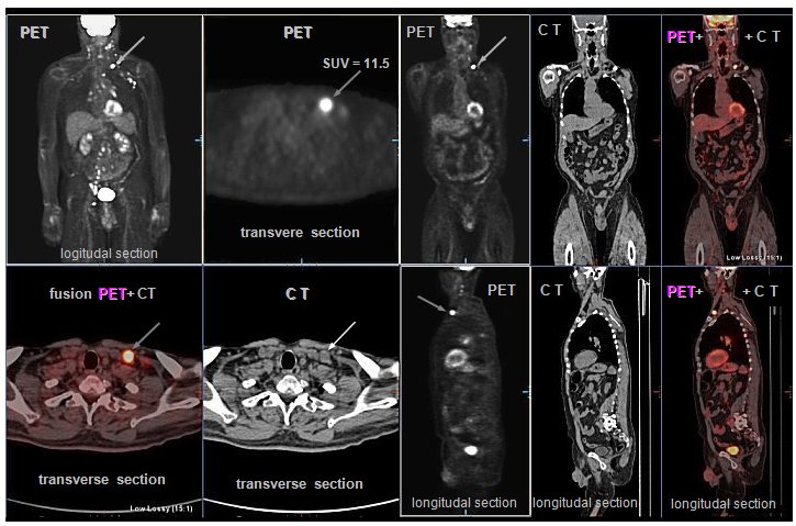 |
|
Example
of PET/CT scintigraphy with 18FDG in a patient with lymphoma.
PET images show multiple foci of increased
glucose metabolism in the lymph nodes of the neck, left
axilla, mediastinum, retroperitoneum, pelvis and groin,
indicating viable tumor neoplasia.
Physiologically, 18-FDG deposited in the brain,
in the hollow of the kidney, bladder, light diffusion in
the liver and spleen, the variable is the accumulation in
the myocardium
The transversal section shows separately a
significant deposit in the area of the supraclavicular (marked by arrows) for the
assessment of metabolic accumulation using SUV values [g/ml] :
The SUVmax of the bearing in the nadklicek is
11.5, with the reference SUVmax liver 2.9 and the
mediastinum 1.4.
(PET / CT images were
taken by
Martin Havel, MD, Ph.D.,
head of the PET / CT department
of KNM FN Ostrava )
|
This method is also suitable for monitoring
the response of tumor tissue to radiotherapy, as it displays
metabolically active tumor tissue, in contrast to inactivated
cells; it is thus possible to monitor the "success" of
the therapy. Among other things, it is able to recognize tumor
recurrence (with proliferating cells) from other structures,
necrotic or connective tissue. The 18F-FMISO and 18F-FETNIM radioindicators show cellular hypoxia,
which is important for tumor angiogenesis and for planning
radiotherapy (radiosensitivity, oxygen effect - see below "Physical
and radiobiological aspects of radiotherapy").
Normal
whole-body scintigram bone
Multiple
metastases (breast ca) to the skeleton
To display bone metastasis, at
an early stage of infiltration, proves best bone
scintigraphy (whole-body scintigraphy in PA and
AP projection, with possibly targeted SPECT images of suspicious
sites) after osteotropic radiopharmaceuticals, which are
phosphate complexes, whose accumulation reflects increased
osteoblastic activity in response to tumor bone destruction.
Planar whole-body scintigraphy of the skeleton is useful to
supplement with a combined SPECT/CT image with
image fusion, to specify the anatomical location of the lesions.
In thyroid cancer, the diagnosis is based on scintigraphy after
application of radioiodine 131
or 123I.
Labeled peptides that
bind to peptide receptors on the surface of some types of tumor
cells are mainly used in neuroendocrine tumors containing somatostatin
receptors (the cyclic peptide somatostatin
is a hormonal substance that has a inhibitory effect on the
production of certain hormones, especially growth; Greek soma
= body, statizo = stand, stop ). An
artificial somatostatin analogue, octreotide, labeled
with indium - 111In-pentetreotide (OctreoScan), or 68Ga -DOTATOC for PET scintigraphy is
used to visualize the respective tumors and to predict the effect
of somatostatin analog therapy. The logical sequence of
diagnostics using these radioindicators is their labeling with
therapeutic radionuclides with application for radioisotope
biologically targeted radiotherapy, see below "Radioisotope therapy",
section "Radionuclide therapy of tumors and metastases".
In addition, some non-specific
indicators of tumors are used, the increased accumulation of
which in tumor tissue is based on their ability to penetrate
pathologically altered permeability of walls and capillaries and
bind within viable cells. Used 99mTc-MIBI and tetrofosmin mainly in lymphomas and mammary
tumor (mammoscintigraphy). In oncological diagnostics, gallium
scintigraphy (mostly planar whole-body imaging, supplemented
with possibly SPECT images) with 67Ga-citrate. Chemically, Ga ions are analogs of Fe ions,
bind to the transport protein transferrin, and accumulate in
proliferating tumor tissues, particularly lymphomas. Gallium-67
scintigraphy is now abandoned and replaced by PET scintigraphy
with 18FDG.
Theranostics using FAIP - mentioned above in "Fibroplast activating
protein FAP and its inhibitor FAPI"
- are under development.
Indirectly, tumor processes can sometimes be inferred from other
scintigraphic examinations, such as dynamic scintigraphy of the
kidneys and liver.
Multifactorial image analysis -
radiomics
Using the methods of "machine learning" and artificial
intelligence, procedures of so-called radiomics
were developed - sophisticated image analysis in conjunction with
statistical processing of data from a large number of patients,
which can recognize even hidden informations,
directly invisible visually. These analyzes can reveal some
similarities and coincidences, helping to refine the likely
diagnosis of tumor types, or predict response to therapy and
course of disease. It is discussed in Chapter 4, §4.7, paragraph
"Multifactorial
statistical analysis of images, radiomics".
Histological examination
If anomalous tissue (neoplasm) that could be of
tumor origin is found by imaging or other examination methods, histological
examination must be performed: a small
sample of tissue is taken by biopsy and then viwed under
a microscope. Histological examination is also performed on
"suspicious" tissues removed during surgery. According
to the shape, size and other characteristics of the cells, it is
usually possible to distinguish whether it is a benign or
malignant tissue and what kind of possible tumor cells they are
(as mentioned above). All this macroscopic and microscopic
diagnostic information determines the optimal way to treat
cancer.
×
Diagnostics
for cancer therapy planning
If the primary diagnosis of cancer is confirmed, the stage of
preparation of therapy begins - a decision on the basic strategy
and methodology of therapy: whether it will be a surgical
solution, chemotherapy, radiotherapy, eventual its combinations
(see "Cancer therapy" below). If radiotherapy
is planned, X-ray CT, NMRI and gammagraphy (especially PET)
images can be used to determine the exact location and
extent of the tumor site and to plot the regions
of interest (ROI) of the irradiated volume - GTV, CTV
and finally PTV in the irradiation plan (see below the section
"Planning of radiotherapy"). The base is now used CT images (respectively NMRI), but these
mainly reflect morphological page, but do not capture the
behavior of biological tissue. It is therefore useful to also
gamagraphic views, especially PET images of the distribution of 18FDG or 18FLT, respectively 18F-choline. By
analyzing these PET images (eg by determining SUV levels - see
§4.2, section "Scintigraphic
image quality and detectability of lesions"),
we can determine the "Biological Target Volume"
(BTV) of tumor tissue formed by viable proliferating
cells. By transferring of these images to a radiotherapy planning
system and computer image fusion (CT, NMRI) +
PET we can then refine the volume of the target
lesion, especially CTV for IMRT radiotherapy. According to the
distribution of tumor cell viability, we can further modulate the
dose within the tumor site and increase (escalation, boost) doses
to risk areas within the tumor.
l Predicting
the response to cancer therapy
Predicting the biological response to planned treatment is a very
difficult task in medicine in general. In cancer therapy, certain
basic information can already be obtained from the results of
primary imaging and histological diagnostics. However, there are
ways to indirectly assess the specific behavior of tumor tissue
for the planned type of treatment using gamma imaging
methods, especially PET.
l Monitoring
the distribution of cytostatics and monoclonal antibodies
The success of chemotherapy depends, among other things, on
whether the cytostatics or monoclonal antibodies used accumulate
(uptake) sufficiently in the tumor foci. Nuclear medicine can be
used to predict the chemotherapeutic effect. Methods for radionuclide
labeling of some chemotherapeutics have been developed:
after "trial" diagnostic application of a small amount
of such labeled radioindicator, we can display its distribution
and assess how selectively it is taken up in tumor tissue (as
well as in healthy tissues that could thus be undesirably
affected by by radiation) - in this way, the respective
chemotherapeutic agent will be taken up during the actual
therapeutic application. A similar "trial" diagnostic
application of a smaller amount of g- radioindicator can be used
in radioisotope therapy (see "Radioisotope Therapy" below).
l Imaging
Dendritic Cell Migration
One of the basic preconditions for the success of immunotherapy
with dendritic cells activated by antigens of a particular tumor
tissue (see "Cancer Therapy" below, "Immunotherapy" section) is their migration to peripheral lymph
nodes and then to the tumor locus. If we label these activated
dendritic cells before their re-application to the body using a
suitable radioindicator (111In-oxin is tested), while maintaining their viability,
we can scintigraphically map their migration to the lymph nodes
after their application.
The predictive role of imaging
cell apoptosis is discussed in the following paragraph.
×
Monitoring
the biological response to cancer therapy
In addition to the primary diagnosis, it is desirable to monitor how
successful the therapy is and what its side effects are on
healthy tissues, organs and the whole organism. In terms of time
relation to therapy, monitoring of biological response can be
divided into prediction of biological effect
before therapy (mentioned above) or at the beginning of therapy,
monitoring of early response during therapy and
monitoring of late response and overall
long-term development disease after treatment.
To assess the late tumor response, the basis for monitoring the
tumor site in CT or NMRI images - a comparison of the size
(volume) of the displayed tumor lesion before and after therapy
to assess the reduction of tumor mass. However, CT and NMRI
images capture only the morphological situation,
not the biological development of tumor tissue and the metabolic
activity of cells - we do not recognize in them what part of the
depicted lesion of different density is formed by viable tumor
cells and what part by necrotized or connective tissue. It is
therefore useful to use "molecular" gammagraphy using
SPECT and PET methods to reliably monitor the tumor response.
These are mainly the already mentioned images of the 18 FDG or 18FLT distribution,
performed before and after therapy (or during therapy), on which
possibly we compare SUV values. Molecular gamma imaging allows
the visualization of important factors influencing the response
of tumors to therapy. Another "line" - radiobiological
modeling - is the assessment of the radiotherapeutic effect
using the quantities TCP, NTCP, UTCP, discussed below in the
section "Prediction of the radiotherapeutic effect - the
probability of cure of a TCP tumor and damage to normal NTCP
tissue".
Immediately after the end of
radiotherapy, no macroscopic change can be detected in
the irradiated tumor - the changes take place first at the
molecular level. Only a few weeks to months apart, these
nitrocellular processes result in the extinction of most of the
cells in the tumor population; only this can be accompanied by
observable morphological changes.
l Early
tumor response - imaging of cell apoptosis
However, functional molecular imaging in gammagraphy
provides other unique possibilities. Radioindicators have been
developed to monitor one of the main radiobiological mechanisms
of cancer therapy (both radiotherapy and chemotherapy): cell
apoptosis. In cell apoptosis (see
§5.2, section "Effect of radiation on cells", section "Cell apoptosis") in the early phase, among other things, irreversible membrane
depolarization occurs, the uncovering of phospholipids
on the cell surface, increased permeability of the plasma
membrane, then at a later phase the integrity of the cell wall is
violated and finally to cells disintegration and their
phagocytosis. It is in the early phase of apoptosis that the
special radiopharmaceuticals shows an affinity for
apoptotic cells *): they either bind to
phospholipids on the surface, or penetrate the cell membrane and
accumulate in the cytoplasm of apoptotic cells. The result is a
selective accumulation of radioindicator in apoptotic cells and
tissues, while they hardly enter in tissues formed by normal
viable cells or necrotic tissues.

By gammagraphic imaging of the distribution of these
radioindicators (it is appropriate to use dynamic
gammagraphy - time factor of accumulation) we obtain positive images of those places, where
apoptosis occurs most intensively - whether due to irradiation,
cytotoxic substances or ischemia. By molecular imaging of the
distribution of cell apoptosis, we can monitor the very
early response of cells and tissues to therapy
(radiotherapy or chemotherapy), already at the beginning and
during therapy. It basically allows the prediction of the
tumor response: we apply "experimentally" one
or two fractions and on gammagraphic images we can assess whether
apoptosis is taking place in the target tissue sufficiently
intensively, or whether there are regions of apoptotic resistance
in the heterogeneous tumor. Early imaging of apoptosis can play a
significant role in biological individual
("personalized") therapy of a particular
patient.
*) Three types of
radioindicators of apoptosis are in the stage of laboratory
development and preclinical studies (see also §4.8 "Radionuclides and radiopharmaceuticals
for scintigraphy") :
- Protein
99mTc-Annexin V (for
SPECT imaging) - binds to phospholipids on the surface of
apoptotic cells;
- 18F-ML-10
[2- (5-Fluoro pentyl) -2-methyl malonic acid] - a small molecule
that penetrates the wall of apoptotic cells and accumulates in
their cytoplasm. Approx. 400MBq is applied.
- Peptide
18F-CP18
[triazole-containing pentapeptide] - maps Caspase-3 activity,
accumulates in apoptotic cells.
Combination of diagnostics
and therapy - theranostics
New diagnostic imaging methods, especially molecular
imaging in nuclear medicine, allow to integrate
individual (personalized) diagnostics and targeted therapy (or
prevention) of serious diseases into a common field, for which it
was newly using the name theranostics (created by composing names: therapy +
diagnostics => Theranostics). Scintigraphy makes it possible to determine the
concentrations of biologically active substances directly at the
sites of their targeted action, which enables optimal and
individual dosing, with the possibility of predicting effects and
monitoring the results of therapy - it is discussed in more
detail in §4.9, section "Theranostics".
Therapy of tumor diseases
In terms of goal and effectiveness, we
generally distinguish between two types of treatment: Curative
therapy (Latin cura =
treatment) with the aim of complete
cure of cancer, especially in the localized stage. In more severe
and advanced cases, then palliative therapy (Latin pallium = mantle),
alleviating and slowing down the course of the disease and its
difficulties. In terms of time sequence, we also recognize two
procedures: Induction therapy - initial
treatment to achieve remission of the disease. After this
primotherapy (possibly also simultaneously), adjuvant
therapy is often applied - auxiliary, supportive or
securing treatment (Lat. adiuvo =
support, help), especially to reduce
the risk of recurrence due to possible micro-seeding around the
original tumor.
The treatment of tumors is currently based
on three main methods: surgery, chemotherapy
and radiotherapy, with these three main
therapeutic approaches are often combined - multimodal
treatment. In the surgical treatment of cancer, physical
removal is performed - resection or ablation
(Lat. Ablatio = removal, distant) of the tumor tissue. It is desirable to remove not only
the primary tumor with the "safety margin", but also,
if possible, other tissues into which the tumor cells could be
infiltrated: these are mainly the surrounding lymph nodes located
in the lymphatic "river basin" of the tumor location (see also above §3.5, passage "Radiation-guided
surgery - sentinel nodes"). In addition to classical surgical techniques, radiofrequency
ablation and stereotactic ablative radiosurgery SRS
(sterotactic radiosurgery) are also used - see the "Stereotactic radiotherapy"
section.
For non-surgical
treatment of cancer, we would ideally need some "magic
missiles" that would penetrate the body in a non-invasive
manner, target and destroy only the tumor cells,
while maintaining undamaged healthy surrounding tissue. Because
tumor tissue is made up of cells that are not very different from
the healthy cells of the surrounding tissues, we do not have such
an ideal and selective "shot": treatment focused
against tumor cells will always more or less damage even some
healthy cells, tissues and organs. However, there are certain
physical and biological factors that at least partially promote
the targeted destruction of tumor cells and minimize damage to
healthy tissues.
In terms of the place of action in the
body, we can divide the therapy of cancer into two methodological
approaches :
l Local
tumor control , in which we try to stop tumor growth and
destroy cells in a particular tumor site of known location and
extent. It is performed mainly by the method of radiotherapy -
targeted delivery of a high radiation dose to the tumor site.
This approach is effective for well-defined tumors of small or
medium size, without distant metastases.
l Systemic therapy
performed by application of suitable
drugs into the organism, which enter the tumor foci and stop the
proliferation or kill the tumor cells there. These include
chemotherapy with cytostatics and biological therapy, and in part
targeted radionuclide therapy. This whole-body systemic action
has its advantages and disadvantages. The advantage is the action
on multiple tumor foci and hidden metastases, the presence and
location of which we sometimes do not even know. The disadvantage
is the side effects on healthy cells and tissues, into which the
chemotherapeutic agents also enter, through the blood and
lymphatic way. Systemic therapy is chosen in cases of more
extensive tumor disease with metastatic infiltration. And also as
an adjuvant therapy to reduce the risk of recurrence and
metastasis.
Below, first will be briefly described
methods of systemic and targeted chemotherapy
and biological treatment, then more detailed methods of targeted radiotherapy
using physical and radiobiological aspects.
Chemotherapy
and biological treatment
Under chemotherapy generally means treating
diseases by administering chemicals - drugs that are the product
of chemical synthesis or isolated from natural materials
(especially plants) - and which cause desirable (bio)chemical
reactions in the organism. Chemotherapy of cancer is most often
performed using cytostatics - substances that
stop or inhibit the growth and division of cells (Greek: kytos = cavity, cell; statikos = stopping). Their preferential antitumor effect is due to the fact
that they act primarily on rapidly dividing cells. However, they
also affect healthy physiologically dividing cells in the body,
which leads to undesirable side effects. A number of cytostatics
are known, which act by different mechanisms and at different
stages of the cell cycle. There are two basic mechanisms of
action of cytostatics :
1. Action on DNA , which disrupts cellular
function, prevents replication, it can be evaluated by the cell
cycle control nodes as irreparable damage ® activation of the internal
signaling pathway of apoptosis (in this respect the
mechanism is similar to ionizing radiation).
2. Effects on other cellular structures, especially microtubules,
which violates the very act of cell division - it acts as a
"mitotic poison". The cells are thus inactivated,
they cannot divide further, they undergo apoptosis
either directly or following a "mitotic disorder" (see
§5.2, passage "Mechanisms of
cell death").
In more detail, four diffrent
mechanisms of action of cytostatics are distiguished, according
to which these substances are divided :
l Alkylation
cytostatics - react with
bases in the DNA, e.g. guanine, by their alkylation - by
transferring the carbon radical group C2nH2n+1 (alkyl). This leads to DNA cleavage or the
formation of a two-stranded junction. This damage to DNA
inactivates cells, prevents them from dividing (DNA strands
cannot untwist and separate), and ultimately leads to apoptosis.
A cytostatic effect has long been observed with nitrogen mustard
analogues. From this group, chlorambucil,
cyclophosphamide or ifosfamide are used (own
cytostatic effect has only their metabolite oxycyclophosphamide
formed in the nucleus), as well as fludarabine and bendamustine
.
Platinum cytostatics also belong to this group.
The longest used cytostatic of this species is cisplatin
(cis- [PtCl2 (NH3)2]),
an inorganic molecule that binds to guanine bases in a DNA
molecule; more recent are the organic compounds carboplatin
and oxaliplatin, where platinum atoms are attached to
cyclic ("aromatic") hydrocarbons.
l Microtubule
inhibitors - react with microtubules
in cells, prevent the formation of a mitotic spindle - mitotic
poisons. These are two types of chemicals that have opposite
mechanisms of microtubular action, but result in similar
cytotoxic effects :
- yew terpenides - taxanes. The
alkaloids paclitaxel (contained in yew Taxus brevifolia )
and docetaxel (from yew Taxus
braccata) are used, which
stabilize microtubule polymers (inhibition of microtubule
depolymerization) and prevent chromosome
separation during anaphase.
- vinca alkaloids - vincristine,
vinblastine, vinorelbine, which bind to tubulin and prevent
its polymerization into microtubules.
l Antimetabolites blocking the synthesis of purine and pyrimidine DNA
bases required for cellular replication. Substances with a
structure similar to purines and pyrimidines - fluoropyrimidines,
especially methotrexate or 5-fluorouracil
(5-FU) preparations are used. More recently, the 5-FU precursor, capecitabine,
is preferably used, from which the active substance
5-fluorouracil is formed by enzymatic transformations only in the
body, preferably in tumor tissue (the
enzyme thimidine phosphorephilase, which participates in
the final phase of the conversion of inactive capecitabine to
active 5 -FU, is contained in tumor cells usually in a
significantly higher concentration than in cells of healthy
tissue - selective effect).
l Topoisomerase
inhibitors in S-phase of the
cell cycle prevent the untwist of the DNA double helix during the
replication process (in which the enzyme topoisomerase
is involved). This leads to the induction of DNA breaks that can
cause cell death. The original substance of this kind was camptothecin,
an alkaloid isolated from the Chinese tree Camptotheca
acuminata. However, its synthetic derivatives topotecan
and irinotecan have more suitable pharmacological
properties.
l Antitumor
antibiotics are originally
substances that inhibit the growth and multiplication of
microorganisms, therefore used in the treatment of infectious
diseases, as well as antifungal agents and the like. They are
secondary metabolites of microorganisms (bacteria, mold), many of
which are now prepared artificially (by synthetic or
semi-synthetic methods). As most of them contain in their
chemical structure several groups of cyclic hydrocarbons
("benzene nuclei") characteristic of anthracene, they
are also called anthracycline antibiotics.
In addition to the antibiotic effect, in some of these substances
have also been found an immunosuppressive effect and a cytostatic,
antitumor, antiproliferative effect. The mechanism of
the cytostatic effect is probably binding to DNA - their
molecules have the ability to be incorporated between DNA base
pairs; DNA breaks occur, intercalation bonds are formed with a
transcription disorder (tight connection of both strands of DNA
prevents its copying before cell division and transcription into
RNA), DNA breaks down (the effect is similar to that of radiation
or alkylating cytostatics). The enzyme topoisomerase is also
blocked, which is involved in changes in the spatial
arrangement of DNA during replication prior to cell division;
when it is blocked, the individual parts of the DNA do not come
together, that break down. An example is doxorubicin, bleomycin,
epirubicin, idarubicin, mitomycin C.
This group also includes, in
part, rapamycin, originally isolated
from the bacterium Streptomyces hygroscopicus discovered
in soil on Easter Island Rapa Nui; it is also called sirolimus (Lat. siro = pit dug in the soil, limus = mud,
sludge). It ranks among the macrolide
antibiotics that block protein synthesis in microorganisms by
binding in ribosomes. Due to its immunosuppressive effects, it is
used in transplants as protection against adverse immune
reactions that can lead to transplant rejection. By inhibiting
the protein kinase (mTOR *), it blocks a number of
intracellular processes, leading to a decrease in cell
proliferative activity. It prevents cells from moving from the G1
phase of the cell cycle to the S phase, causing cell cycle
arrest. It increases the sensitivity of tumor cells to
radiotherapy and the effectiveness of chemotherapy. Rapamycin
thus also belongs to the group of kinase inhibitors
listed below, where its new derivatives temsirolimus and
everolimus are used.
*) Rapamycin, mTOR
mTOR (mammalian Target Of Rapamycin ) - this
very misleading name comes from the fact that the relevant
protein kinase was first discovered when rapamycin was applied to
the ca of breast. An alternative name is "mechanic
target of rapamycin". It was later shown that mTOR also
works in other types of tumor cells. The PI3K/Akt/mTOR signaling
cascade is significantly involved in the process of
carcinogenesis, and its inhibition may be an important factor in
cancer therapy.
l Antioxidants
are known primarily as cancer
prevention. However, it has been shown that some antioxidants
(such as reveratrol, genistein, baikalein) damage DNA
and kill dividing cells. This could be used in anticancer
therapy. Their advantage is that, despite their genotoxicity,
they do not have mutagenic effects. So far, it is in the stage of
biological research.
l Bisphosphonates
act as inhibitors of
osteoclastic bone resorption. They can therefore be used for the
secondary treatment of bone tumors, especially
metastases, where they act primarily against bone erosion; it is
not a cytostatic. Effective nitrogen bisphosphonate is mainly zoledronic
acid. In combination with eg docetaxel, there is an additive
synergistic antitumor effect - potentiation of the cytostatic
effect.
Individual cytostatics are sometimes combined,
eg FOLFOX (oxaliplatin + 5-fluorouracil + folic acid), XELOX
(capecitabine + oxaliplatin), FOLFIRI (5-fluorouracil +
irinotecan) and others. A common disadvantage of classical
cytostatics is their systemic non-specific effect
- they act not only on tumor cells, but also on healthy
physiologically dividing cells. This leads to a number of often
serious side undesirable (toxic) effects. Therefore, a new
variant of targeted "transport" of a suitable
cytostatic preparation directly to cancer sites is being tested,
using microcapsules up to 5 mm in size. Such tiny capsules, formed from a suitable
organic substance and carrying a cytostatic inside, pass through
the vascular system and the fine blood capillaries after
application. They can be monitored sonographically or by magnetic
resonance imaging; the moment they reach the tumor, they can be
disrupted by an ultrasound wave, releasing the cytostatic at the
required place - in the tumor.
Chemical structure of some cytostatics used in chemotherapy of
cancer
Targeted
biological therapy
In recent years, knowledge of molecular biology
and genetics has developed rapidly, revealing, among other
things, complex mechanisms of cellular communication and
specific molecules that are important for malignant cell
transformation. These could become the target of specific
therapeutic interventions: to identify and target certain
structures in tumor cells in order to prevent further
proliferation of tumor tissue. Targeted biological
treatment is based on these mechanisms, the strategy of
which is directed against selected types of molecules and their
signaling pathways involved in the malignant behavior of cells of
the respective tumor types. Together with more effective therapy,
these procedures make it possible to reduce undesirable
side effects. Currently, the main interest is
focused on the so-called growth factors (stimulating
cell growth and division) and their receptors, especially EGFR,
HER2 and VEGF (see below).
A new class of drugs is being
developed that selectively block the activity of these oncogenic
proteins, with minimal damage to normal cells. These are mainly
two groups of substances with different mechanisms of action :
l Monoclonal
antibodies
are special proteins from the group of immunoglobulins (or fragments thereof), which are
obtained from a cloned population of one species
of activated B-lymphocyte from the plasma of an immunized
organism. The monoclonal antibody therefore has precisely defined
properties and specifically binds to the
respective receptors. Some monoclonal antibodies seek to approach
an ideal therapeutics - a "magic
arrow" that would hit only target
pathological cells and have no detrimental effects on
other healthy cells. However, this cannot yet be achieved 100%
..!..
Structure of monoclonal antibodies
The molecular weight of monoclonal antibodies is around 150 kDa.
The structure of immunoglobulin protein
molecules is often schematically represented by the shape of the
letter " Y " (in the figure on the left - a).
The branched part - arms - consists of two heterodimers, it is
formed by four polypeptide parts, arranged in two
mirror-identical pairs of "heavy" and
"light" chains. They are internally
linked by a disulfide bond (SS). Light and heavy chains contain constant
and variable regions. The variable
regions, located at the ends, contain short amino acid sequences (sometimes called "hepervariable"), that determines the binding antigenic
specificity of an antibody. Therefore,
these arms are referred to as Fab (Fragment antigen
binding). The "foot" in the antibody scheme consists
of two heavier chains, referred to as Fc (crystallizing fragment
) . This constant region of Fc is
responsible for the effector functions of the
antibody (interaction with T-lymphocytes, macrophages) -
activation of systems leading to the destruction of target cells.
Preparation of monoclonal antibodies
- hybridoma technology
Because we can't cultivate directly the desired clones of
activated B-lymphocytes efficiently enough, the preparation
of monoclonal antibodies is complex biochemical
technology. Very suitable "auxiliary carriers"
for preparing of monoclonal antibodies have proven to be myeloma cells (otherwise known as tumor cells of myeloma,
a hematooncological disease of the bone marrow caused by
uncontrollable proliferation of myeloma cells), which, due to their unlimited replication
capabilities and longevity, are very suitable for cultivation and
fusion in vitro. Thus, the formation of these
"helper" myeloma cells is first
induced in experimental laboratory animals. These are then
harvested and cultivated in vitro. Meanwhile, in another
laboratory animal, an injection of a particular antigen elicits
an immune response with B-cell activation and
subsequent production of antibodies. These B-lymphocytes are
taken from the lymphatic system (usually a
spleen sample) of the animal used and then fused
in vitro with a colony of myeloma cells. From this fusion, hybrid
cells (called hybridomas)
are formed, which retain the properties of
both myeloma cells and the desired B-cell clone, divide rapidly,
and produce antibodies of
B-cell (used in the fusion). Using special separation methods,
only hybridomas producing only one desired
antibody clone - a monoclonal antibody - are
selected from them.
This
resourceful biotechnology was first developed in 1975 by
G.F..Kohler and C. Milstein in the Molecular Biology Laboratories
of the University of Cambridge and the Institute of Immunology in
Basel (for this method they received the Nobel Prize in 1984).
 |
Monoclonal
antibodies .
a, b) Schematic diagram and illustration
of the basic structure. c) Mouse
monoclonal antibody. d, e, f) Chimeric,
humanized and human antibody. |
The laboratory animals used in the process of
preparing monoclonal antibodies are almost always mice, so that
the mouse monoclonal antibody (c) is primarily
generated. For its human use can sometimes lead to undesirable
immune reactions - immunogenicity
due to the development of human-anti-mouse antibodies HAMA
(Human Anti-Mouse Antibodies). On the one hand, this
prevents (makes it impossible) the binding of the monoclonal
antibody to the target antigen and, on the other hand, can also
lead to immune anaphylactic reactions. Therefore, there is an
effort to replace parts of the molecules (which do not encode
antigen binding regions) with human
immunoglobulin sections - to humanize antibodies
using sophisticated biochemical-genetic methods ("genetic engineering"). From the original hybridone line producing murine
antibodies of a given targeting, the RNA was prepared and further
in a reaction catalyzed by an enzyme reverse transcriptase, a complementary
cRNA -. By polymerase reactions were multiplies segment
encoding the antigen binding site. By this genetic sequence are
replaced the corresponding region in the human immunoglobulin
gene. Thus formed resulting new gene is inserted into a suitable
recipient mammalian cell, which then synthesizes a monoclonal
antibody with a predominant human immunoglobulin content.
The humanized monoclonal antibody has constant regions from a
human immunoglobulin, and only the variable region, encoding
antigenic specificity, is derived from a murine antibody. The
antibodies thus transformed have the desired antigenic
specificity and show only minimal immunogenicity. In this way, chimeric
(cross) antibodies (content of about 60% human antibody), humanized
(content of more than 90% human antibody) or 100% human
antibody are generated - in Fig. d), e), f). The more
"animal" the antibody, the greater the risk of
immunogenicity can be expected. Humanization of monoclonal
antibodies leads to a reduction in unwanted immunogenicity, but
on the other hand also to a possible reduction in their
effectiveness ...
Antibody fragments
The larger the protein molecule, the slower and more difficult it
is to penetrate the target tissues. Therefore, instead of
"whole" antibodies, suitable antibody fragments
are prepared, containing only regions with preserved antigenic
specificity. Most commonly, these are Fab´ fragments
containing domains necessary for antigen binding, but not part Fc
this interacting as effector.
Nano-antibodies - Nanobodies
The most consistent "miniaturization" of
monoclonal antibodies are the so-called nanobodies,
consisting only of the variable domain of the antibody with the Fab
H heavy chain, without the light chain domain and, of
course, without the Fc part. The name "nanobody"
comes from its namometric size - length approx. 4 nm and width
approx. 2 nm, molecular weight is only around 15 kDa. However,
the ability of nano-antibodies to bind the relevant antigen
remains the same as for conventional antibodies. In addition,
nanoantibodies exhibit better stability, hydrophilicity and water
solubility, deep tissue penetration, and rapid clearance from the
bloodstream, contributing to their very good resulting binding
affinity under various conditions.
Nanobodies have excellent
properties especially in the diagnostic imaging of tumor tissues.
Images with a high signal-to-noise ratio can be obtained already
in the early period after application, due to the rapid
accumulation of the nanobody and rapid depletion in the blood.
However, the therapeutic
efficacy of nanobodies alone is limited by the absence of an
effector Fc fragment. However, if the nanobodies are chelately
conjugated with a beta or gamma therapeutic radionuclide, the
therapeutic potential is preserved - biologically
targeted radionuclide therapy.
Nomenclature of monoclonal antibodies
The nomenclature of monoclonal antibodies is elaborated so that
the basic type and the most important properties
(targeting) of a specific preparation (antibody) can be
identified from the name. The name consists of 4
parts: prefix - designation of the target structure - biological
type (origin) - suffix (it is always - mab: monoclonal
anti body)
:
| Monoclonal
antibody name : |
| prefix - |
- target
structure - |
- biological
origin - |
- suffix |
variable
(individual) |
- ci
(r) - vascular system
- tu (m) - tumor
- li (m) - immune system
|
- m
(o) - mouse
- xi - chimeric
- zu - humanized
- u - human |
- mab
( monoclonal
anti body) |
Example are rituximab, a
chimeric monoclonal antibody (-xi-), whose variable portion
mediating contact with the tumor cell CD20 antigen (-tu-), is of
murine origin and the remainder of the antibody is of human
origin.
In the literature, other more detailed
divisions are sometimes given - in the target structure for
specific types of tumors (-co (l) - colon
tumor, -go (v) - ovarian tumor, -ma (r) - breast tumor, -me (l )
- melanoma, -neu (r) - nervous system, -pr (o) - prostate tumor,
-vi (r) - viruses .....), in biological
origin other possibilities (-a- rat, -e -
hamster, -i- primates, .....); however, we
do not encounter these names in practice... In some preparations,
in addition to the monoclonal antibody itself, the name is also
given biochemically conjugated substances (eg ibritumomab
tiuxetan - ......).
Biological effects of monoclonal antibodies
In order to produce the desired effect (therapeutic
or diagnostic), the antibody must first
reach the target tissues and cells. Therapeutic monoclonal
antibodies are administered intravenously by slow infusion of the
solution. Monoclonal antibodies have relatively large molecules
with masses around 150 kDa, min. 100 times larger than
conventional cytostatics. Therefore, they have slower
distribution kinetics and more difficult to penetrate tumor
tissue, with slow diffusion through the interstitial space. Their
distribution in the tumor is usually inhomogeneous, especially in
larger tumors.
Monoclonal antibodies have the
ability to react with the particular antigen against which they
are targeted. If the target structure is a receptor ligand, this
ligand is neutralized. If the target structure is a receptor on
the surface of the cell membrane, the signaling pathway
associated with it is blocked. Many monoclonal antibodies thus
have inhibitory effects on certain ligands and
signaling pathways (or sometimes
stimulatory ones).
A frequent goal of treatment
is the elimination - kill of a certain type of
cells - the depletion process. The condition for binding
to target cells is the presence of appropriate receptors.
The antigen-binding complementarity of an antibody is given by
the variable regions at the ends of the Fab chains, while the
fixed Fc region mediates subsequent effector functions on target
cells. After successful binding of the antibody, three different
mechanisms of the resulting cytocidal effect can occur :
- Activation
of complements - membrane glycoproteins C1-C9, which by
their proteolytic effects attack cytoplasmic cell membranes and
cause their penetration. The cell dies
and the released chemicals cause an inflammatory reaction with
the accumulation of leukocytes (cf. §5.2,
passage "Mechanisms of
cell death").
- Induction
of phagocytosis - fixed Fc region of bound antibody (lower part of the letter " Y " in
the scheme) specifically binds to the Fc
receptor of some types of leukocytes, especially macrophages,
which thus recognize and subsequently phagocytose tumor cells.
- Induction
of apoptosis after antibody binding to the cell surface,
with destruction of mitochondria and proteolytic caspase chain (detailed explanation in §5.2., passage "Apoptosis";
in the picture on the top right "External
signaling pathway of apoptosis").
Immunogenicity of
Monoclonal Antibodies
Monoclonal antibodies, as immune-active agents, when administered
to the body can form "anti-antibodies against antibodies",
which can neutralize their effect and, in
addition, to causing adverse anaphylactic effects
- has already been discussed above. Immunogecality most often
occurs in murine antibodies (HAMA, in about 10%), rarely in
chimeric antibodies, very rarely in humanized. Before using
murine antibodies, it is therefore desirable to perform a
laboratory biochemical test for HAMA antibodies,
its possible positivity should then be a contraindication
to the use of these products.
Use of monoclonal antibodies
In addition to oncology (see below), monoclonal antibodies are
also used against autoimmune diseases, organ transplant
rejection, inflammatory diseases. Also as antibacterial and
antiviral.
Monoclonal antibodies are
mainly used in oncology for stand-alone targeted
biological therapy of cancer (see below). In addition,
cytotoxic substances or radioisotopes can bind to them, which
only "guide" these antibodies, approach or bind them to
the target cells - antibody conjugates with
suitable effector components are formed.
Radiolabeled antibodies -
radioimmunoconjugates
An important new method of biologically targeted therapy
of cancer is the combination of targeted binding of monoclonal
antibodies with the biological effects of ionizing
radiation from radionuclides. Radioimmunoconjugates
have a beta or alpha radionuclide bound in an antibody molecule,
for a biologically targeted radionuclide therapy
- see below "Radioisotope
therapy with open emitters".
The monoclonal antibody does not serve as a primary
therapeutic here, but provides the "delivery" and get
closer of the radioactive substance to the tumor cells. The
advantage of these radioimmunoconjugates is that in order to
achieve a biological effect, it is not necessary to bind them to
each tumor cell, but emited radiation by the effect of "crossfire" has a radius of action of
several tens of cell diameters (see below Fig.3.6.8 in "Radioisotope therapy").
They are therefore effective even in the neighboring cells which
have insufficient expression of a tumor antigen.
Some monoclonal antibodies
labeled with a gamma or positron radionuclides, are used
in nuclear medicine as radioindicators in scintigraphic
diagnostics- §4.8 "Radionuclides and
radiopharmaceuticals for scintigraphy", passage "Immunoscintigraphy".
It is mainly in tumor diagnosis, but also, for
example, in the diagnosis of inflammatory foci using antigranulocyte
monoclonal antibodies.
Monoclonal Antibodies in Oncology
A number of monoclonal antibodies are used in oncology
therapy, some of which are briefly listed :
Cetuximab - a chimeric monoclonal antibody that
competitively binds to the extracellular domain of epidermal
growth factor EGFR (HER1) and inhibits the binding of other
possible tumor growth activators; panitumumab
has similar effects .
Trastuzumab (herceptin)
acts as a monoclonal antibody against HER2 (Human Epidermal
Receptor), binding to the extracellular domain of HER2 and
thereby blocking epidermal growth factor access to its receptor;
this prevents activation of the signaling pathway of cell
processes and tumor growth (which is HER2 -
positive). Pertuzumab, which
binds to the dimerization domain of HER2 and thus prevents its
dimerization with other HER receptors, has similar effects. The
combination of trastuzumab + pertuzumab is being
tested to increase the effect of HER2-signaling blockade
(possibly + docetaxel), which shows synergistic activity. The
combination of herceptin with aromatase inhibitors (such as
anastrozole or ietrozole) has also been tested in
hormone-dependent tumors. And in general, herceptin in
combination with the chemotherapeutic agents capecitabine
or 5-fluorouracil and cisplatin is indicated in
various HER2-positive metastatic tumors.
Bevacizumab (Avastin)
is a humanized monoclonal antibody to Vascular Endothelial Growth
Factor (VEGF), which captures circulating VEGF in plasma, thereby
inhibiting tumor neoangiogenesis. Ranibizumab
(Lucentis), which is
used in ophthalmology in the treatment of vascular-related
macular degeneration of the retina, has similar effects.
Rituximab - a chimeric monoclonal antibody of
the IgG1 type, specifically directed against the CD20 antigen, is
a frequently used preparation in malignant B-lymphomas.
Ipilimumab is a monoclonal
antibody that activates CTLA-4 targeting, where
cytotoxic T cells can recognize and destroy tumor cells
(it turns off the inhibitory mechanism and allows T cells
to function). It is used to treat melanoma, non-small cell lung
cancer, ca bladder and ca prostate.
Nivolumab is a human IgG4 anti-PD-1
monoclonal antibody, also acting as a control node inhibitor,
that blocks activated T cells from
attacking tumor cells. It is also used in malignant melanoma (in
combination with ipilumomab), lung ca and kidney ca.
Atezolizumab acts as an inhibitor of
PDL1 programmed cell death ligand. It is mainly used in non-small
cell lung ca.
Another possible mechanism
involved in the anti-tumor effect of some monoclonal antibodies
is the "labeling" of a cell on the surface of which the
relevant receptor is present; the cells thus labeled are then
attacked and destroyed by the body's immune processes. The
efficacy of monoclonal antibodies in tumor therapy depends on the
presence and function of appropriate receptors
on tumor cell membranes. If these receptors are scarce, or are
dysfunctional or mutated, the antibody is ineffective ...
Monoclonal antibodies can also
be "carriers" to which a suitable chemotherapeutic
or radionuclide binds. A long-used radioactive
preparation of this species is Ibritumomab Tiuxetan
labeled with 90Y (Zevalin) for non-Hodgkin's lymphomas. More recently, lilotomab
labeled 177Lu,
targeted against CD37, is used here. However, the 177Lu or 225Ac labeled anti-PSMA
ligand (PSMA-617) in prostate cancer appears to
be the most promising, which is able to cure even advanced
metastatic hormone-independent prostate cancer.
For more details see below "Radioisotope Therapy", passae "Radioimmunotherapy".
Dual-targeted
(bispecific) monoclonal antibodies
Various factors are involved in cancer (as well as some other
serious diseases - inflammatory, autoimmune, degenerative) and
there are a number of complex processes taking place with
multiple signaling pathways between cells. Although monoclonal
antibodies (MAb) can effectively affect specific signaling
pathways, it is often difficult to achieve satisfactory curative
results with one given preparation. Therefore, different types of
chemotherapeutical are sometimes combined. However, this can
bring additional problems with unwanted interference, side
effects, the possibility of unwanted immune responses.
In the field of monoclonal antibodies, however, an alternative
"more elegant" solution is also possible in principle:
Develop such antibody molecules that have two binding
sites aimed at two different antigens
of the given process. These so-called bispecific
antibodies (BsAb) with double targeting
("two in one") can then show better
therapeutic effects than classical unidirectionally targeted
monoclonal antibodies. Two mediators are targeted by a single
molecule.
Various specific ligands
binding to different receptors can be incorporated into the Fab
arms of antibody molecules in several ways. Either by
cross-linking two antibodies with two different pairs of variable
Fab fragments with different antigen binding. Or, instead of one
of the chains, e.g. "b", another "b' " with a different targeting
is chemically attached to the Fab arm - a Fab'
fragment is created. Or, alternatively, heavy and light chain
variable regions cloned from two different antibodies are created
in the IgG antibody. There are other more complicated options...
We briefly list some
bispecific antibodies that have already found clinical
application :
-> Blinatumomab
in malignant B-lymphoid cells in non-Hodkinson's lymphoma,
specific for CD19 and CD3 on effector T-lymphocytes.
->
Mosunetuzumab is a monoclonal antibody used to treat follicular
lymphoma. It binds bispecifically to CD20 contained in
B-lymphocytes and to CD3 found in T-cells. T-cells are thereby
stimulated to destroy lymphoma tumor cells.
-> Emicizumab
is a bispecific antibody for the treatment of hemophilia A. It
binds to both activated coagulation factor IX and factor X, whose
activation it mediates.
-> Amivantamab
is a bispecific monoclonal antibody used to treat non-small cell
lung cancer (a special type with an
insertion mutation of exon 20 of the epidermal growth factor
receptor EGFR). It targets the epidermal
growth factor (EGF) receptor and the mesenchymal-epithelial
transition (MET) receptor.
-> Cadonilimab
binds simultaneously to PD-1 and CTLA-4 antigens, which are
expressed at much higher levels in tumor tissues compared to
normal tissues. These two targets mediate increased cellular
cytotoxicity and cellular phagocytosis. Bispecific cadonilimab (which replaces the combination of nivolumab and
ipilimumab) shows promising efficacy in
cervical, gastric, hepatocellular carcinoma.
-> Faricimab
(RG7716) is used in ophthalmology for the therapy of
vascular-related macular degeneration. It targets both the
vascular endothelial growth factor VEGF-A and the angioprotein
inhibitor ANG-2. It stabilizes the blood vessels in the retina
and shows better effects than the currently used aptamer
pegaptamib (Macugen)
or the monoclonal antibody ranibizumab (Lucentis).
l Mimetic antibodies, Affibody
In addition to "real" monoclonal antibodies, so-called mimetic
antibodies are also used - peptides or small proteins
(with a molecular weight of about 3-20 kDa), which like
antibodies can bind to antigens, but which are structurally not
similar to the relevant antibodies (the
name comes from the Greek mimesis = mimicry, imitate). The main representative of these substances are the
so-called affibodies consisting of three helices
with 58 amino acids with a molecular weight of about 6 kDa. Their
use for diagnostic imaging and targeted therapy is in
development.
l Kinase
inhibitors (thyrosine kinase
inhibitors) are substances that block the signaling pathways of
certain kinases (one or more), thereby inhibiting cell
division and stimulating apoptosis. This can lead to slower tumor
growth and attenuation of tumor angiogenesis. Kinases
are enzymes (§5.2, section "Cells
- basic units of living organisms",
section "Proteins, enzymes, kinases"), which transfer the phosphate group from the adenosine
triphosphate ATP to the acceptor, which has an OH group - the
phosphorester of the acceptor molecule is formed. The tyrosine
kinase transfers the phosphate to the hydroxyl group of the
cyclic amino acid tyrosine bound in the protein, thereby
activating the protein. Tyrosine kinase inhibitors
(tinibs) are small molecules that bind
to an appropriate site in ATP (adenosine triphosphate) to prevent
phosphorylation of substances that are part of the intracellular
signaling pathways by which a chemical signal captured by a
receptor on the cell surface is transmitted to target structures
in the cytoplasm or in the core. One of the important targets of
biologic therapy is the epidermal growth factor receptor
EGFR signaling pathway (Epidermal Growth Factor
Receptor), also known as a human epidermal receptor, Her-1
(human epidermal receptor 1), a transmembrane
glycoprotein (molecular weight about 170000). Another kinase that
affects the regulation of cell growth, including angiogenesis, is
the serine/threonine kinase mTOR (mammalian target
of rapamycin). Thus, mTOR inhibitors may interact in
particular by attenuating angiogenesis.
Inhibition of kinases involved
in oncogenic signaling pathways may suppress the proliferation of
a given tumor cell clone. A certain advantage of these substances
is that (unlike large protein molecules) they can penetrate cells
by passive transport, so that
their activity is not linked to the presence of the respective receptors on the membranes of the tumor
cells.
Gefitinib
is a quinazoline derivative that inhibits EGFR growth receptor
tyrosine kinase activity (especially in the EGFR activating
mutation), with erlotinib having a similar effect. Lapatinib binds to the
intracellular portion of the HER2 growth receptor and inhibits
its tyrosine kinase activity; it also acts as a dual
inhibitor - in addition to HER2, it also acts on the
intracellular activity of the HER1 receptor (ie EGFR). Imatinib
primarily blocks BCR-ABL tyrosine kinase in some
leukemia species; newer and more effective inhibitors of this
type are nilotinib and dasatinib. The
multikinase inhibitors sunitinib and sorafenib
suppress the kinase activity of platelet-derived growth factor
receptors, VEGFR and others (KIT, FLT3, ...) - they act as inhibitors
of angiogenesis. For this purpose, the new mTOR kinase
inhibitors temsirolimus and everolimus
(derivatives of rapamycin - sirolimus mentioned above in
the "anthracycline antibiotics" category),
which block the P3K/Akt/mTOR phosphatidylinositol-3-kinase
signaling pathway, are also being tested. The kinase
inhibitor vemurafenib, which specifically inhibits the
V600-mutated form of the B-raf protein, is also being tested;
shows promising results in the treatment of malignant melanoma.
In some cases, it is useful to combine
monoclonal antibody therapy with an appropriate tyrosine kinase
inhibitor - for example, in a HER2-positive tumor, trastuzumab
and subsequently lapatinib.
l Aptamers (Lat. aptus = capable, Greek meros = part)
are short fragments of RNA or DNA
(oligonucleotides, peptides; molecular weights 3-18 kDa) -
specially prepared and sequenced ligands with high binding
affinity to specific target molecules. They take on different
three-dimensional structures, they are able to bind to
different biomolecules (antibodies, growth factors,
hormones, enzymes, amino acids). They can act as targeted inhibitors
and also as "carriers" suitable therapeutic substances
- "escort" aptamers.
Their use, so far experimental, is an alternative to monoclonal
antibodies. Aptamers can be produced artificially by biochemical
methods in a wide range: RNA serves as a "library" of
nucleotides, from which ligands of desired properties are
prepared by repeated combinations with tumor antigens and
selections (SELEX method - Systematic Evolution of
Ligands by EXponential enrichment). With a bit
of exaggeration, we can say that here we are artificially
"imitating" the natural evolutionary process of natural
selection (however, the selection here is
not made by nature, but by a researcher - a biochemist). The selected aptamers created in this way can then be
sequenced and produced artificially by biochemical methods; in
this they have an advantage over monoclonal antibodies (which are
prepared by immunizing of laboratory animals). In a sense,
aptamers can be thought of as man-made, synthetic chemical
antibodies.
An example is pegaptanib,
which binds to the vascular growth factor VEGF and thus prevents
it from stimulating angiogenesis. Pegaptamib is currently used in
ophthalmology (under the name Macugen ,
bound to a polyethylene glycol polymer) to
suppress unwanted excessive angiogenesis in macular
degenerationof retina; however, it is now gradually being
replaced by the monoclonal antibody ranibizumab (Lucentis), or most recently by
the bispecific monoclonal antibody faricimab.
The designation of
aptamers by radionuclides could be promising - either g- radionuclides for
scintigraphic diagnostics, or b
or a radionuclides for biologically targeted radionuclide
therapy. For example, an anti-tenascin-C aptamer labeled
with 99mTc
and 111In
(for glioblastoma), or an Anti-MUC1 aptamer labeled with
99mTc or 186Re (for breast
cancer) is tested.
A significant problem
with aptamers is the way to "deliver" aptamers to
specific pathological tissues and cells in the body - so that
they are not damaged or broken down or destroyed *). Aptamers
have a short lifetime (a few minutes to hours) and are quickly
degraded from the bloodstream in the kidneys. Experiments are
carried out with binding of aptamers to the surface of nanoparticles.
After the nanoparticles come into contact with the cell, the
aptamers react with specific receptors on the cell membrane and
influence the processes in the cell.
*) This disadvantage does not apply to
pegaptanib, which is not used systemically, but is applied
directly to the eye (intraocular injection into the vitreous) and
is therefore locally bioavailable well in the vascular system of
the retina.
Biological treatment of cancer includes several other
special procedures :
l Gene therapy of tumors is still in the stage of laboratory
development, but its more significant application can be expected
in the near future. Two different pathways of gene tumor therapy
are being developed :
- A straightforward
procedure within tumor cells seeks to "correct" a
genetic variation that has led to malignant cell transformation
by a targeted change. The difficulty of this approach lies not
only in the laboratory biochemical complexity of introducing
specific genetic information using a suitable RNA vector and
reverse transcriptase, but also in the fact that several
different genetic changes (mutations) are involved in the
malignant transformation of cells. This is probably not only the
changes in known DNA coding sequences, but also in the as yet
unexplored "genetic junk", "unnecessary" DNA.
- In an
alternative approach, the target of gene therapy is not directly
tumor cells, but other cells and tissues that, under the
influence of targeted genetic intervention, are modified so that
they can begin to produce certain active substances that
effectively block tumor growth.
l Telomerase
inhibition is so far an
experimental method directed against one of the above-mentioned
factors of carcinogenesis: overcoming the Hayflick limit of cell
division - their immortilization - due to active telomerase
acting in tumor cells. Antitelomer vaccination is
performed by applying telomerase to the body in order to elicit
an immune response that would kill the telomerase in the tumor
cells and thus prevent their unrestricted division.
Unfortunately, telomerase inhibition also affects other cells,
such as hematopoiesis, where telomerase performs its
physiological function. Experiments with combined telomerase
inhibition together with inhibition of tankyrase to
potentiate the effect are also being experimented (telomerase and
tankyrase work "synergistically in tandem
cooperation"). Therapy based on telomerase inhibition can
only be successful where telomerase is active. Recently, however,
it has been found that telomerase is not the only factor in the
immortilization of tumor cells, but mechanisms of homologous
recombination of telomere sequences work similarly (it is
discussed in §5.2, part "DNA, chromosomes, telomeres").
This "bad news" somewhat reduces the promising
therapeutic potential of telomerase ...
l Hormone
therapy of tumors is based on
the fact that some types of tumor cells contain receptors
for hormones - they are hormone dependent,
their origin and development is dependent on the level of certain
hormones. In breast cancer cells there are estrogen receptors, in
prostate tumors for androgens.The growth of tumor cells can
inhibit hormones with the opposite effect (hormone antagonists)
or prevent the synthesis of hormones (castration in the prostate,
ovariectomy in the breast ca), both methods are often combined,
with the possibility of blocking receptors in
hormone-dependent forms of tumors (especially breast cancer),
which leads to the cessation of tumor cell proliferation.
Selective estrogen receptor modulators such as tamoxifen
are used for this purpose. Aromatase inhibitors (an enzyme involved in the synthesis of estrogens from
testosterone, estradiol is formed) such as anastrazole,
ietresol, formestane, also block the production of
estrogens.
l Immunotherapy generally represents a targeted intervention into the
body's immune system for a therapeutic purpose - to restore,
strengthen, or modify the functions of the immune system.
Unfortunately, in advanced cancer, the immune system usually does
not respond to the tumor cells of one's own body (immunosuppression).
One of the goals of tumor immunotherapy is to
label and "make visible" tumor cells for the body's
immune system, which can then "take care" of their
destruction. Genetic changes in tumor cells result, among other
things, in the emergence of new antigens, different from
non-tumor cells. These tumor antigens may become a desirable
target for immune responses, but only if we "serve"
them properly to the immune system.
As the vector
for the purpose of immune antitumor
vaccination are particularly useful group of
special cells from white blood cells called dendritic
cells of the immune system, with many numerous
protrusions on the surface (Greek dendron =
tree, the cells have tree-shaped branched protrusions - dendrites). These cells initiate immune responses, differentiate
foreign and the body's own substances (they can recognize various
antigens, including tumor cells), are capable of phagocytosis of
foreign particles. Subsequently, they mature, exposing on their
surface parts of absorbed proteins (in our case tumor antigens)
and thus activating T-lymphocytes, which
completes the "destructive" immune response involving effector
monocytes transforming into macrophages. Dendritic
cells can thus become an effective tool for autologous
cellular immunotherapy, which stimulates the body's own
immune system to "engage" in the fight against cancer.
 |
The procedure of anti-tumor
immune vaccination consists of several stages :
- Sampling of tumor tissue,
isolation and cultivation of tumor line cells;
- Collection of peripheral blood,
separation of leukocytes and monocytes by leucopheresis;
- Growing in vitro cultures
of native (immature) dendritic cells;
- Activation of dendritic cells by
uptake of cells of a given tumor line (their antigens);
- From the activated (mature)
dendritic cells, which expose tumor antigens on their
surface, a final vaccine is prepared, which is applied
back to the organism;
- Activated dendritic cells migrate
to the lymph nodes, where they activate effector T cells;
- Activated cytotoxic T-lymphocytes
recognize and kill tumor cells (N). |
Dendritic cells can be obtained by culturing
for several days from monocytes extracted from the patient's
peripheral blood *). In addition, a sample of tumor
tissue is taken. If then (in vitro, using
disrupted or apoptotic tumor cells) dendritic cells absorb the
tumor antigens from the tumor tissue and then thus stimulated
cells are applied back into the body, they have the ability to
stimulate the immune system for "fight" against to the
original tumor cells. Subsequently, activated effector T-cells
travel into the tumor site and selectively attack the tumor
cells. The method is still in the stage of experimental clinical
studies.
*) To obtain a larger number of leukocytes
and monocytes, a special sampling separation method called leucopheresis
or leukapheresis (Greek leukosis = white
, these are white blood cells - leukocytes; afairesis
= take ) is used.: the blood circulates through a
centrifugal separation unit, where the leukocytes are separated,
while other components of blood (especially plasma) return
to the patient's circulation.
Although tumor cells produce
antigens that, in principle, the immune system can use for their
identification and subsequent targeted destruction by cytotoxic
T-lymphocytes (CTL), here exters an inhibitory mechanism
of antigen associated with the CTLA-4 proteinn, the binding of
which to the CTL receptor shuts down the cytotoxic response. This
mechanism, on the one hand, prevents excessive adverse immune
reactions (autoimmunity), but on the other hand allows tumor
cells to survive. The anti-CTLA-4 monoclonal antibody ipilimumab
(MDX-010), which binds to CTLA-4, blocks its inhibitory
function and allows CTL to continue to destroy tumor cells, has
been shown to enhance anti-tumor CTL immunity.
Another newly tested method based on the
immune system is the blocker protein CD47 - anti-CD47.
The CD47 protein is physiologically present on the surface of
blood cells and its task is to protect them from its own white
blood cells. However, many tumor cells also have the CD47 protein
on their surface, which protects them from white blood cells and
therefore cannot be destroyed by the immune system. By applying
an anti-CD47 blocker, the immune system is stimulated to
kill the tumor cells. Although there is also a loss of blood
cells, which need to be supplemented ...
The above-mentioned monoclonal
antibodies also belong to the category of immunotherapy.
Molecular biological chemotherapy (immunotherapy, monoclonal
antibodies) is often suitable to combine
with classical cytostatics - to enhance the therapeutic effect.
For example, the combination docetaxel with trastuzamab
is used, 5-fluorouracil + oxaliplatin (FOLFOX), or 5-fluorouracil
+ irinotecan (FOLFIRI), with bevacizumab or cetuximab,
capecitabine with trastuzumab or lapatinib,
and several others. Recently, the application of cytostatics and
monoclonal antibodies labeled with therapeutic
beta-radionuclides, which represent combined
molecular chemo-radiotherapy, has been tested. Some such
methods and preparations are mentioned below in the part "Radioisotope therapy",
section "Radionuclide therapy of tumors and metastases"
and "Radioimmunotherapy".
Abscopic effect
In some cases a synergistic effect of
immunotherapy and radiotherapy is observed. Rarely occurs
so-called abscopic effect
(i.e. off target - Lat. ab
= outside, away; scopium = target, angle of wiev) when after local radiotherapy certain tumor lesions,
recede systemically even other lesions that have not been
irradiated. Radiotherapy may induce an immunoeffect
against further metastases of the same tumor (for more details,
see §5.2, passage "Bystander-Abscopal effect ").
Alternative
methods
In addition to chemotherapy and radiotherapy, some alternative
methods of cancer therapy are sometimes used or tried. We will
mention two based on temperature :
¨ Hyperthermia
- local heating of the target tissue to a temperature higher than
43 °C, causing inhibition of DNA and protein production,
together with a reduction in tumor vascularization. Tumor tissues
usually respond more sensitively to heat than normal healthy
tissues. In healthy (normally perfused) tissue, vasodilation
occurs when heated, which removes heat more efficiently through
the blood and reduces heating. The vessels formed by
neoangiogenesis in the tumor are chaotic, functionally imperfect
and possibly compressed with tumor mass. Tumor vessels are not
able to effectively regulate blood flow, so when the tumor is
heated, vasodilation does not occur and the tumor heats up more
than the surrounding healthy tissues. In particular, large and
hypoxic tumors, which are less sensitive to radiotherapy, are
therefore suitable for the treatment of hyperthermia.
At temperatures above 43 °C, denaturation of
proteins (including cell membrane proteins
and microtubules, causing changes in membrane potentials and ion
concentrations) begins to occur, leading to
cell death, predominantly by necrosis.
In addition, heat stress express the HSP heat stress proteins (Heat
shock proteins), the most common is Hsp70, which in addition
to its anti-stress effect (bind to a
hydrophobic amino acid sequence partially damaged proteins, which
allow the correction to the correct spatial arrangement; further
promote the degradation of damaged proteins), their "chaperone" activities allow binding to
the antigen, and transport to cell membranes, where these
antigens are presented (via the
transmembrane glycoprotein MHC 1) and thus stimulate
the immune system - the formation of cytotoxic
T-lymphocytes specific for a given type of tumor. Furthermore,
enzymatic cell repair mechanisms (such as excision repair, homologous recombination,
non-homologous end-joining - see §5.2, passage "Repair
processes") are heat-sensitive - thermolabile.
This can be used for the synergetic effect of
combining hyperthermia with radiotherapy or chemotherapy -
thermoradiotherapy (hyperthermic radiotherapy) or
thermochemotherapy.
Non-invasive heating of the tumor inside the body
can be achieved by electromagnetic waves or ultrasound. Recently,
a promissing method of high-intensity focused ultrasound
HIFU (High-Intensity Focused Ultrasound) has apeared.
Focusing of ultrasonic waves is achieved using a specially shaped
(concavely curved) transducer. High-intensity ultrasound focuses
on the tumor, within which energy is converted into heat. The
tissue temperature rises to 65 °C, during which thermal
ablation occurs - the temperature kills the tumor cells,
but when properly targeted, does not damage the surrounding
healthy tissues. A rapid and short-term increase in local
temperature (within 2-3 seconds) destroys the target tissue by coagulation
necrosis - we literally "cook" the tumor, while
the surrounding structures are not damaged. HIFU therapy is
suitable to perform during MRI navigation.
Furthermore, the hyperthermic
method could activate chemotherapeutic drugs directly in tumors.
The chemotherapeutic is "wrapped" in heat-sensitive
microscopic particles ( liposomes - particles coated
with a fat layer) and applied to the bloodstream. At a normal
body temperature of about 37 °C, the particles pass through the
blood vessels undisturbed and have no toxic effects on the body.
When they enter the tumor in this way, they can be locally heated
by the focused HIFU waves to a temperature higher than 42 °C, at
which point the liposome envelope becomes porous and the drug is
released directly into the tumor. The therapeutic effect of the
drug is thus targeted in the tumor, with the minimization of
undesirable side effects in other parts of the body.
¨ Cryotherapy (Greek cryos = cold )
(also called cryosurgery) consists in the application of
very low temperatures in order to destroy the target tissue (cryodestruction).
It is used in various medical fields (dermatology, ophthalmology,
gynecology, surgery) even for the treatment of non-malignant
diseases. In oncological indications, it is the destruction
of a tumor by freezing by introducing freezing probe - a
cryocauter, cooled mostly by liquid nitrogen.
The rapid freezing of the tissue causes its damage by the
formation of ice crystals inside and outside the cells, with
subsequent necrosis of the frozen cells. To achieve the desired
effect, the target tissue must be cooled to below -20 °C with a high
freezing rate approx. 30 °C/sec. Slow freezing would dehydrate the
cells, which could survive after thawing. On the contrary, the
subsequent thawing should be much slower so that the cells are
exposed for a long time to mechanical damage by recrystallizing
ice and also to the toxic action of the intracellular fluid, in
which the concentration of salts and ions has risen sharply. The
cryotherapy method is used for tumors accessible by direct
application of the cryocauter, most often for skin lesions.
Note:
Issues of chemotherapy and other non-radiation
methods we have outlined here only briefly and marginally, due to
the complexity of the interpretation of the principles and
current possibilities of cancer therapy; further details of
complex biochemical reactions (often not yet fully explored) in
chemotherapy and biological treatment lie beyond the scope of our
physics-oriented treatise on radiotherapy ...
Risk of quack therapy ?
In addition to scientifically proven knowledge and working
methods (at least relatively), in all fields of human activity
there are occasionally unproven and erroneous claims and the
promotion of methods that do not work, but many people believe
them - see "Quackery versus science". It often occurs in the area of ??our health and
life - in medicine. Biological and psychosomatic factors tend to
be so complex and diverse that, in addition to serious scientific
research and the discovery of real causes, it provides
considerable scope for unqualified fabrications and sometimes
fraud.
Some people do not trust modern medicine -
sometimes from their own experience (doctors failed to find the
cause, they made a mistake somewhere, insufficient
communication,...), or from the stories of their acquaintances
(there is a tendency to exaggerate and generalize negative
experiences). Or because they believed ("fall for the
scam") the miraculous promises of charlatans. If a person
with such a mentality gets cancer, it may happen that instead of
therapy in the oncology department with proven medical means
(according to the current state of science and technology), he
decides to visit some pyramid that stops the growth of cancer, or
allows himself to be treated by the incantation of some witch
with miraculous powers abilities (I admit
that even this can sometimes be positive in isolated cases due to
the placebo effect). When, after a long
time, such a patient realizes on his own that it is ineffective,
it may already be too late for real causal
treatment..!..
Trust in the self-saving effects of some
miracle drugs promoted by fraudulent distributors can lead to a
similar risk.
Radiotherapy
of tumor diseases (cancer) is based on the effects of ionizing
radiation on living tissue (the mechanisms
of these effects are described in detail in §5.2 "Biological effects of ionizing
radiation").
Can radiation heal
cells ?
The name "Radiotherapy" may give the
impression that "radiation can cure the damaged or
mutated cells?". Non! - ionizing
radiation can only kill cells !
The therapeutic effect here consists in the targeted
elimination of tumor cells in the organism.
Sufficiently high doses of ionizing
radiation are able to inactivate and kill cells,
in this case tumor cells. In tumor tissue, it is
necessary to destroy mainly clonogenic stem cells, the
unrestricted division of which causes cancer. Radiation damage
to the tumor's vascular supply can also play a significant
role in stopping tumor growth. Radiotherapy can thus be an
effective local (or local-regional) method of
cancer therapy (and possibly also some
other focal diseases and disorders).
The goal of classical
radiotherapy is the reproductive sterilization
of clonogenic tumor cells by radiation-induced apoptosis. In
stereotactic radiotherapy, in addition, an ablative
approach is even applied - immediate destruction of
cells by necrosis, caused by a high single dose of radiation.
Radiotherapy - local treatment
Unlike the systemic chemotherapy and biological treatment
discussed above ("Chemotherapy and
biological treatment"), external radiotherapy is a local method
that is able to successfully eliminate specific tumor lesions in
known locations. If the cancer is disseminated - metastatic,
the final result of external radiotherapy is problematic: after
the successful treatment of one lesion, progression may occur
in other places...
Radiation eradication of tumor cells can
be part of effective curative therapy to
completely cure cancer, especially at the localized stage. In
more severe and advanced cases, then palliative therapy,
alleviating and slowing down the course of the disease and its
difficulties. After surgical removal of the tumor lesion, the
so-called adjuvant radiotherapy is often applied -
auxiliary, supportive or securing treatment after surgery, to
reduce the risk of recurrence due to possible micro-infiltration
in the vicinity of the original tumor. In certain cases,
preoperative so-called neoadjuvant radiotherapy is used
before surgery - to reduce the extent of the tumor ("downstaging") and
thus improve its operability, as well as to reduce the viability
of tumor cells and thus reduce the risk of local or metastatic
infiltration (during tumor surgey, tumor cells may be release
into the environment, lymphatic system and bloodstream). The
surgery is then performed about 6 weeks after radiotherapy, when
the acute radiation symptoms have disappeared and late changes
have not yet occurred (see below "Side
effects of radiotherapy - radiotoxicity").
Perioperative
(intraoperative) radiotherapy is rarely used - direct
irradiation of the tumor site or its remnant, uncovered during
surgery. This method is complicated by the fact that it is
necessary to either install an irradiation device in the
operating room, or to be able to quickly transport the patient to
the irradiation room and then back to the operating room. From this point of view, mobile devices with a
miniaturized X-ray tube or an electron gun and a target, which is
applied to a target lesion (eg a cavity after resection of the
tumor itself) and irradiated with low-energy X-rays (with an
energy of several tens of keV) with a high dose and ionization
density, which can in principle also be used in laparoscopic
operations.
The
majority of this §3.6 will be devoted to radiotherapy
of tumors.
Combination
chemo-radiotherapy
To improve the results of cancer treatment, in some cases it is
useful to combine the two above-mentioned therapeutic modalities:
concomitant - accompanying,
complementary, additional therapies, a special case of multimodal
therapy. The benefits of simultaneous application of
chemotherapy with radiotherapy can be basically of three types :
l Additive
effect - the effect of radiotherapy and
chemotherapy for the destruction of tumor cells adds up (without
direct interdependence). The additive effect of chemotherapy
occurs on both the irradiated cells of the target volume and
chemotherapy can also cause the elimination and attenuation of
micrometastases outside the irradiated volume.
l
Radiosensitizing effect - chemotherapy enhances the
biological effect of ionizing radiation on cells (increased DNA
fragility due to chemically bound cytostatics, inhibition
of DNA repair mechanisms, or by appropriate temporal influencing
of the cell cycle to a phase more sensitive to radiation, eg G2)
- potentiation radiotherapy. One such
cytostatic agent that increases the sensitivity of tumor cells to
radiotherapy is sirolimus (rapamycin- mentioned
above as an anthracycline antibiotic); the combination of
sirolimus + radiotherapy is better tolerated in terms of side
effects than the combination of radiotherapy with most other
chemotherapeutics.
Tumors with increased expression of EGFR (= HER1) and HER2 growth
receptors generally have increased radioresistance, as the
intrinsic signaling pathways of these receptors are involved in
activating DNA repair processes upon ionizing radiation damage.
By applying targeted biological treatment against growth factor
receptors - cetuximab, trastuzumab, gefitinib, lapatinib, etc.,
the growth factor signaling pathways are interrupted, DNA repair
capacity is reduced and therefore an increase in tumor radiosensitivity
can be expected.
l Anti-repopulatory
effect - cytostatics, and in particular
some targeted biologic therapies, such as monoclonal antibodies
against growth factors, reduce the repopulation of tumor cells
during time-prolonged fractionated radiotherapy, leading to a
more efficient killing of a larger fraction of tumor cells by
radiation.
In chemosensitive tumors, chemotherapy can
also cause a reduction in the volume, a
kind of "shrinkage" of the tumor (similar effect to neoadjuvant
chemotherapy). Such a reduced tumor is then easier to treat
with radiotherapy, both by reducing in the number of tumor cells
alone and possibly by improving blood flow and oxygenation,
which leads to increased radiosensitivity due to the oxygen
effect. The resulting effects of chemo-radiotherapy are
analyzed in more detail below in the section "Prediction
of the radiotherapeutic effect".
Physical
and radiobiological factors in radiotherapy
The optimal therapeutic effect of radiation is achieved by
co-production of two types of factors :
¨ Physical factors -
selective introduction of a sufficiently high dose of radiation
into a pathological lesion by a suitable irradiation technique,
using physical properties of radiation. We
will discuss these physical aspects in detail in most of the text
of this chapter; here we first briefly analyze the
radiobiological aspects :
¨ Biological factors -
the type of tumor and the properties of the surrounding healthy
tissue. For radiotherapy is very important radiosensitivity
of specific tumor type, as well as the difference in radiation
sensitivity between tumor and healthy tissue *). Lymphomas,
leukemia, seminoma are highly radiosensitive. Carcinomas, such as
prostate adenocarcinoma, are moderately radiosensitive. Gliomas,
sarcomas, melanoma, squamous cell carcinoma of the skin are
radioresistant.
*) It is the risk of damage to the
surrounding healthy tissues and organs, that is the main
limiting factor in delivering a sufficiently high dose to the
tumor site. By critical organ or tissue we mean
a structure in the organism whose radiation damage would have
serious health consequences, or in the case of vital organs even
death. Therefore, a certain so-called tolerance dose
must not be exceeded during radiotherapy in these critical organs
to prevent their irreversible damage.
Therapeutic ratio
For the possibility of achieving a good curative effect
of radiotherapy, the most important thing is often not the actual
radiosensitivity of the tumor tissue, but rather the ratio of the
radiosensitivity of the tumor and surrounding healthy tissue -
the so-called therapeutic ratio TR (Therapeutic
Ratio). It can be quantified in different ways *): by
comparing the dose-response curves of cell survival N/N0 (Fig.5.2.3c) for tumor and surrounding healthy tissue (from the
ratio of gradients or areas under these curves), or with the help
of biologically effective dose BED, or by comparing the
probability quantities TCP and NTCP (see below "Prediction of radiotherapeutic
effect - TCP, NTCP"). To quantify the therapeutic ratio of TR, we obtain
different indices TRN/No , TRBED , TRTCP , whose numerical values are different and must be
considered separately. The therapeutic ratio can be improved by
fractionation of radiation, combination with chemotherapy,
improvement of oxidation of the tumor site (overcoming hypoxia,
use of densely ionizing radiation with high LET) - is discussed
below.
*) Therapeutic options were previously
evaluated using the so-called Paterson graph,
which shows the dependence of the relative number of killed tumor
cells on the radiation dose. The same graph also shows the dose
dependence of the risk of irreversible damage to the surrounding
healthy tissue. In the favorable case, the curve for tumor tissue
is on the left, the curve of the probability of complications of
healthy tissue is shifted on the right. The width of the gap
between these two sigmoidal curves is sometimes called the therapeutic
width. More complex evaluations are now performed using
special TCP and NTCP graphs - see below "Prediction of radiotherapeutic effect - TCP,
NTCP".
Time fractionation of irradiation
Tumor tissue that is in a state of intense (pathological) cell
division is usually more sensitive to radiation
than healthy tissue (it is discussed in
more detail in §5.2 "Biological effects of
radiation"). Fractional irradiation is usually
used, where the total dose is divided into a number of smaller
daily doses *), applied over a number of days (approximately 3-5 weeks, see below "Fractionation in practice").
*) Single irradiation of
small lesions with a high dose (or substantial reduction of the
number of fractions to 2-5) allows the Sterotactic radiotherapy thanks to the possibility of very
precise targeting of the canceroletal (or
radioablative) dose into tumor, with less load on the surrounding
critical tissues and organs.
There are basically two
reasons for the time fractionation of the radiation dose :
1. Healthy tissue cells usually have a higher
ability to repair radiation damage than tumor cells.
When dividing the dose into a number of smaller fractions,
applied individually after completion of the repair processes in
the cells, the resulting cumulative biological
effect on tumor tissue is generally higher than on healthy
tissue, which has a greater regenerative capacity.
Radiobiological aspects of radiation fractionation are discussed
below. The radiotherapeutic effect on the tumor tissue itself is
sometimes expressed by a probabilistic quantityTCP,
defined below.
2. In each tissue, including tumor tissue, there are cells
at different stages of the cell cycle, in which
they have different radiobiological sensitivities. Therefore, a
single dose of radiation may not be optimal for all cells, which
may not be in the most sensitive phase. If the total dose is
divided into several fractions with a suitable time interval,
then after each such dose, the part of the cells which has just
reached the most sensitive phase at that time can be most
efficiently destroyed.
Dependence of radiation-biological
effect on dose and its time schedule - LQ model
The dependence of deterministic radiation effect on dose and its
time schedule is analyzed in detail in §5.2 "Biological effects of ionizing radiation", part "Dose-biological effect
relationship", where the so-called linear-quadratic
model (LQ) is introduced - see the section "LQ
model", Fig.5.2.3c. There
is also derived a basic equation of dependence between dose D
and the surviving fraction of cells N/No in (semi)logarithmic scale :
-ln (N / No ) = a .D + {2. [(1-e - l .T ). (1-1 / l .T)] / l .T } . b .D 2 -
ln2.T / T2r
,
where a and
b are
the factors indicating the probabilities of damage a- and b -processes, T
is the irradiation time, l is the rate of cell repair, T2r is the doubling
time of the number of cells by repopulations. The coefficient in
angle brackets {...} is the so-called Lea-Catcheside factor, which
captures the effect of cell repair during irradiation. The linear
member a.D
is dominant for early-reacting tissues (with higher cell
proliferation), the quadratic member b.D2
is more pronounced in late-reacting tissues. Basic
linear-quadratic dependence N/No on the dose (D) is shown on a reduced scale for
illustration below, in Fig.3.6.0 a. The general equations of the
LQ model have rather theoretical significance; for
practical applications in radiotherapy, simpler special
relationships for specific irradiation conditions and
techniques are derived from them (see below "Irradiation
fractionation"). These general radiation-biological
mechanisms are approached in practice by some other individual biological
influences, which are sometimes difficult to include in
one LQ model.
Individual biological
factors - " 6 R "
Biological effect of ionizing radiation in
relation to the radiation dose, its time schedule and possibly
volume distribution is influenced by several factors and
biological processes during irradiation (whose names can be
formulated so as to beginning with the letter "R")
:
×
Radiosensitivity
of the irradiated tissue is given by the sensitivity of
individual cells to radiation damage; it generally varies
considerably for different types of tissues. In the
linear-quadratic model, radiosensitivity is implicitly contained
in the coefficients a and b. However, each tissue is in fact a heterogeneous
cell population, containing cells with different
radiosensitivity - with different coefficients a, b: the resulting
survival curve [ln (N/N0)] (D) is then a superposition of several different LQ
curves.
× Reparation
is the ability of cells to repair their important structures,
especially DNA, damaged by ionizing radiation or other influences
(cell repair processes are described in
more detail in §5.2 ,
section "Repair processes").
Repair processes have a time dimension: they take a
certain amount of time (given by the coefficient l - the rate of cell
repair), and the repair must be carried out before further damage
prevents successful repair. The repair processes, which take
place continuously during irradiation, thus lead to a "dose
rate effect". In the LQ model, the repair is included
in the additional coefficient RG º {...} in the b- member.
×
Repopulation
Upon exposure to ionizing radiation, some cells die, but other
cells normally divide and may eventually replace destroyed cells.
This cell repopulation and tissue regeneration is
provided by clonogenic stem cells. Repopulation is quantified by
the rate of recovery of a certain number of cells, or the time T2r of
doubling of the number of cells. In the LQ model, the
repopulation is captured in the additive term RP º ln2.T/T2r . Exponential
tumor growth is assumed here, which is approximately met
only in the initial stages of growth of miniature tumors, with
the growth of the tumor the growth rate slows down.
×
Redistribution
Different cell types at different stages of the cell cycle
are differently sensitive to ionizing radiation. During the
actual exposure, the so-called redistribution of
cells can occur - a change in the
representation of different types of cells in the tissue *).
During irradiation, more clonogenic stem cells and cells in the
G1 and G2 phases of the cell cycle decrease, while effector
daughter cells and M and S phase cells in general will be
relatively greater representation. Stem cells are more
radiation-sensitive than mother cells (see also §5.2 ); the goal of radiotherapy is to kill tumor stem
cells. The redistribution effect leads to changes in
intratumorous radiosensitivity during irradiation, as well
as to specific side effects on healthy tissue *) .
*) Complicated
temporal dynamics of cell redistribution
The processes of cell redistribution during irradiation have a
complex time dynamics and occur both in the
tumor target tissue, as well as in the surrounding healthy
tissues affected by radiation. In the first part of the exposure,
clonogenic stem cells are declining faster, because they are (due
to the faster cell cycle) more sensitive. This is followed by a
gradual loss of daughter effector cells, which reduces the
function of the irradiated tissue. A regulatory mechanism is in
place to preserve tissue functionality, leading to a partial loss
of division asymmetry stem cells, which begin to divide
symmetrically into two effector cells each; thereby (at the cost
of loss of stem cells) the functionality of the tissue is
temporarily preserved. If exposure continues, as the number of
clonogenic cells falls below a certain critical level (threatened
by stem cell disappearance and subsequent tissue death), another
regulatory mechanism occurs to trigger accelerated stem
cell repopulation to maintain their population necessary
for tissue regeneration. This reduces the production of effector
daughter cells, which are no longer sufficient to cover the
functional need for tissue - there is a clinical manifestation of
deterministic radiation effect in healthy tissue, acute radiotoxicity
(cf. the passage "Acute radiation sickness" in §5.2; on the side effects of radiotherapy - early and late
radiotoxicity, is briefly discussed below - "Strategic
goal of radiotherapy"). If the exposure continues
(fractional irradiation) and the tolerance dose of the tissue is
not exceeded, the proliferated stem cells can produce effector
cells in sufficient numbers to ensure the basic (albeit reduced)
functionality of the tissue; some "emergency steady
state" may occur with the reduction or disappearance of
previous acute problems in healthy critical tissue. In the case
of a tumor lesion, on the other hand, it is desirable to deliver
a sufficiently high dose to overcome the repopulation of
clonogenic tumor cells - to reduce them to a zero level, leading
to the death of tumor tissue.
× Reoxygenation -
oxygen effect
The atoms of oxygen, contained in water and other
molecules in the tissue, play a dominant role in the
radiobiological effect - oxygen radicals and
peroxides generated by radiation effectively damage DNA in cells.
During tumor growth, as the tumor mass increases, there is often
a lack of oxygen in the cells, so-called hypoxia.
Hypoxia occurs especially when the tumor grows faster than the
capillary vascular network of tumor neoangiogenesis. In hypoxic
tumor cells, a much slower metabolism takes place (they often
remain in the G0 phase of the cell cycle) and during irradiation there
is a lower formation of oxygen radicals - these cells therefore
have reduced radiosensitivity, they are radioresistant.
The surviving fraction of these radioresistant hypoxic cells may
be a potential risk of cancer recurrence.
Irradiation can cause some reoxygenation
(reduction of hypoxia) of tumor foci: reducing the number of
tumor cells reduces total oxygen consumption and reducing the
tumor can also reduce intratumorous pressure, loosen capillaries,
and improve blood flow and supply to the remaining cells. The
effect of reoxygenation is positive for radiotherapy -
it increases the radiosensitivity of the tumor tissue *) and thus
improves the therapeutic effect when using doses with
limited tolerances of healthy tissues. The oxygen effect is
significant especially when using sparsely ionizing radiation
(photon radiation g or X is most often used), where the indirect radical
mechanism of the radiation effect predominates. In densely
ionizing radiation, where there is an increased proportion of
direct intervention mechanism (and also increased recombination
of radicals), the effect of oxygen (oxygenation) on
radiobiological effects is less significant (see "Hadron
radiotherapy").
*) Influence of oxygen content on
radiosensitivity - so-called oxygen effect - is
sometimes expressed by the factor OER ( oxygen
enhancement ratio ), which indicates the relative increase
in the biological efficiency of radiation in the presence of
oxygen (normooxidation) compared to its absence. The
ratio of OER between completely anoxic and normoxic tissue
reaches a value of about 2.5.
The processes of
redistribution and reoxygenation vary widely between different
tumor tissues and are difficult to predict. It is therefore
difficult to introduce them into the LQ model, they are usually
considered separately. All these individual effects can result in
changes in the radiation sensitivity of cells
and tissues during irradiation, leading to further
deviations from the dependencies of the ideal LQ model. Recently, the influence of the so-called bystander
effect has also been discussed (see §5.2 "Biological effects of ionizing radiation", passage "Bystander-Abscopal effect"), which could perhaps somewhat correct the effect
of mild inhomogeneities in tumor tissue irradiation - increase
the effect in underexposed parts target tissues.
×
Volume factor - Radiation
volume
The sixth factor, which is sometimes important for the resulting
radiobiological effect in the tumor tissue and especially in the
critical organs, is the volume distribution of the
radiation dose - the size of the irradiated volume (Radiated
volume). At the cellular level, the biological effect is
determined primarily by the size of the dose; the same is true
for local tissue effects. Therefore, in organs with a serial
arrangement of functional parts (spinal cord, esophagus,
intestine, optic nerve), the resulting radiobiological impact is
dependent on the maximum local dose: at high local dose, the
serial organ can be radiation "disrupted" with
irreversible impairment of its function. In contrast, volume
organs with parallelby arranging functional parts
(lungs, liver, etc.) they tolerate high local irradiation well,
even above 80Gy (causing failure of only negligible functional
parts), but even relatively weaker irradiation (approx. 20Gy) of
their entire volume can significantly impair their function - the
resulting organ effect depends on the average dose per
whole organ.
For various radiation sensitivities of tissues and organs and
their division into serial and parallel,
see §5.2,
section "Local tissue and organ radiation effects".
Irradiation
fractionation according to the LQ model
The parameters a, b, l, T2r in the equation of the dependence of the surviving
fraction of cells on dose D and irradiation time T
according to the linear-quadratic model, as well as other
biological factors of redistribution and reoxygenation, are
different for individual tissue types, especially for healthy and
tumor tissues. This dependence can be used to optimize
the resulting radiation response of tumor tissue with respect to
healthy tissue using a suitable time schedule - fractionation
- of radiation dose. The total radiation dose D is
distributed into individual fractions d i (i = 1,2, ..., n)
with irradiation times t i . For a detailed analysis, the general Lea-Catcheside
dose-time integral (derived in §5.2, "LQ
model") can be used in the
equations of the LQ model. However, in the case of evenly
distributed fractions d i º d (D = n.d), the
duration of which t i = t is short in comparison with the total duration T
of radiotherapy treatment, the simplified equation can be used
for total therapy, substituting the following
values for dose and time variables :
l In the linear a - member we substitute the
total dose D = n.d, which is proportional to the number of
damages by the double a -process (a-processes in individual fractions do not interact with
each other, they are composed linearly).
l In
the quadratic b- member it is important, that the square of the dose D2 in the LQ model
during fractionation is not D2 = n2.d2 (as would result
directly from the squaring of the relation D = n.d), but the
number of fractions n appears in 1.power:
b .D2 = b .n.d2. The exact derivation
of this fact lies in the solution of the general Lea-Catchesid
integral. However, it also follows from the physico-biological
mechanism : according to the theory of dual radiation action (see
§5.2, section "Intervention and radical theory of radiation
effect"), quadratic dose dependence refers to a single
absorbed dose, in this case to dose d of one
fraction - b .d2; the total effect is formed by the sum of n independent
fractions, ie n.b.d2. The individual fractions here do not interact with
each other.
l Time
T in the Lea-Catchesid coefficient at quadratic b-member we replace
by the exposure time of the irradiation fraction t (during
which the repair occurs).
l For
the time T in the additive repopulation member, we take
the total time T of the given radiotherapy (assuming that
the continuous repopulation of cells occurs during the whole
therapy at approximately constant rate).
The resulting equation of the LQ model for (regularly)
fractionated irradiation with the total dose D = n.d
during the total time T divided into n fractions
with sub-doses d and exposure times t , will then
be :
-ln (N / No) = a .D + n . { 2. [1- (1-e -l .t / l .t)] / l .t }. b .d - ln2.T / T2r .
The repair mechanism may be more pronounced in LDR
brachytherapy, especially in the late stages of permanent
brachytherapy (see "Brachyradiotherapy" below). In EBRT teletherapy, the
exposure time of the individual fractions t is short
(about tens of seconds to several minutes) due to the rate of
cell repair: t << 1 / l
, so the Lea-Catcheside factor {...} can be set
equal to 1 (there are no interactions between
the individual fractions) and the resulting effect will be :
-ln (N / No) = a .D + b . n .d 2 - ln2.T / T2r = ( a + b .d) .D - ln2.T / T2r .
When a single short-term irradiation (t = T << T2r), does
not appear the additive repopulating member (ln2.T/T2r ) ® 0.
For a basic analysis of
fractionated radiotherapy can be neglected temporal effects
reparation and repopulation - we come from the basic equation LQ
model :
E
º -ln
(N / No) =
a .D + b.D 2 ,
where the logarithm of the surviving fraction of cells N/No is denoted for
brevity by E (a kind of "irradiation
efficiency"). With regularly fractionated irradiation, D =
n.d, so simple algebraic adjustments gradually give (justification of first power of n1 at b .D2 was given above) :
E = a .n.d + b .n.d 2 = n.d (a + b .d) = D. a . [1+ (b / a) .d] = D. a . [1 + d / (a / b)] .
We see that the radiobiological effect increases with increasing
dose on fraction d and also depends on the value of the a/b ratio for the
irradiated tissue. At high doses per fraction, the radiation
effect is significantly higher; at a given dose D, the
effect is highest when applied once, in one fraction (n = 1, d =
D). If we apply a larger number of fractions n with a
lower dose d to the fraction, we must increase
the total dose D to achieve the same biological effect .
Biologically effective dose BED
The logarithmic irradiation efficiency E is therefore
proportional to the total dose D with the coefficients a and [1 + d /(a/b)]; it is this
second coefficient that expresses the relationship of the
biological effect to the fractionation of the dose and the a/b ratio of a given
tissue. To express the dependence of the biological effect of
radiation on dose fractionation, a derived biophysical dose
quantity biologically effective dose of BED (biological
dose equivalent) is introduced :
BED º E / a = D. [1 + d / (a / b)] .
It can be said that BED = (physical dose) x
(proportionality coefficient); this proportionality factor [1 + d
/ (a/b )]
(relative efficiency) shows how the biological effect of
irradiation depends on the fractionation and the ratio a/b for a specific
irradiated tissue. Since limd ®0 BED = D, the BED is a fictitious dose that
would lead to the same biological effect if the total dose D
were supplied in an infinitely large number of infinitesimal
fractions (or for an infinitely long time with an infinitesimally
low dose rate - if however, we neglect the time factor of cell
repair and repopulation).
Specific BED values are
expressed in dosage units [Gy] provided with an index
given by the numerical value of the a/b ratio
for a particular tissue - BEDa/b
. E.g. a dose of 60Gy, applied in 30
fractions of 2Gy, will form in the early reacting tissue
(fast-growing tumor tissue, skin) with a/b = 10, biologically
effective dose of BED10 = 60. (1 + 2/10) = 72 Gy10 , while in late-reacting tissue (lungs, liver, kidneys)
with a/b = 3, BED3 = 60. (1 +2/3) = 100 Gy3 .
The concept of BED is
important above all as a useful tool for comparing the
effects of different fractionation regimes: the total dose D1 applied in n1 fractions d1 gives the same
(equivalent) biological effect as the dose D2 in n2 fractions of size d2 if it leads to the same BED value: D1.[1 + d1/(a/b)] = D2. [1 + d2/(a/b)]. Also, the
above-mentioned therapeutic ratio of TR radiation
sensitivity of tumor tissue and surrounding healthy tissue can be
quantified as the BED ratio for tumor tissue "TU" and
normal healthy tissue "NT": TRBED = BEDTU / BEDNT .
LQL model
In hypofractionation regimens with high doses per
fraction (d > 5, 10 or more Gy/fraction), which allow
the advanced conformational techniques of stereotactic
radiotherapy and HDR brachytherapy described below, a certain discrepancy
was shown between expected and observed effects: the classical LQ
model at these higher doses per fraction somewhat overestimates
the biological effect of radiotherapy, predicting higher damage
to normal NTCP tissue. As if the curves of the surviving fraction
of cells -ln (N/No) (on a log-linear scale) at higher doses actually
showed an increased proportion of the linear component than the
quadratic. To capture these clinical findings, use is sometimes
empirical model modification LQ called LQ-L model
(linear-quadratic-linear), which for higher doses / fraction
(greater than 2. a/b , in practice > cca. 6Gy) adds additional linear
component increasing the surviving fraction of cells. Other
modifications of the LQ model lead to similar results -
generalized gLQ model, USC (universal survival curve), KN
(Kavahagh-Newman) model, PLQ (Pade Linear Quadratic), LQC model
(linear-quadratic-cubic), see §5.2, part "Deviations and modifications of the LQ model".
Fractionation in practice
The same radiation dose applied in a shorter time (at a higher
dose rate) has greater biological efficiency - cf. also Fig.5.2.3
in §5.2, part "LQ model".
From a radiobiological point of view, the most effective would be
a single irradiation *) of a given deposit with
the required radiation dose of several tens of Gy. However, the
problem here would be the high acute radiotoxicity
to the surrounding healthy tissues, which always receive a
certain (albeit smaller) dose of radiation together with the
target foci. Therefore, it is necessary to divide
the curative radiation dose into a larger number of smaller parts
- fractions. By suitable fractionation it is
possible to achieve that in the time interval between fractions
there is a partial reparation and regenerating
healthy tissue, which is then able to tolerate the load of the
next dose. However, this also increases the tolerance of the
tumor cells (although usually less than in the cells of healthy
tissue), so that it is necessary to increase the total
dose to the tumor site.
*) However , let us consider still point 2 in the
paragraph "Time fractionation of
irradiation"..?..
The most common fractionation,
normofractionation, consists in the
application of about 2Gy 1 x per day (5 days a
week), for a period of 5-8 weeks (5w-8w), total dose
about 60-80 Gy. From a radiobiological point of view, the optimal
fractionation scheme depends on the type of tumor, whether it is
slow or fast growing. In fast-growing tumors, the so-called hyperfractionation
is used, in which more smaller doses (approx. 1.2 Gy) are applied
at shorter time intervals, eg 2-3 x per day, to limit the rapid repopulation of clonogenic
tumor cells. The slower dividing cells of healthy tissues (due to
the time interval between fractions) can be regenerated, the risk
of late radiotoxicity is reduced. The whole irradiation process
is often shortened and accelerated here - so-called accelerated
radiotherapy. Are used classically 2 fraction/day, as well as the
CHART mode (Continuous Hyperfractinated Accelerated
Radiotherapy), hyperfractionated irradiation 3x day, and continuous even over the weekend. The opposite
procedure, so-called hypofractionation, when
only 2x or 1x weekly is irradiated, it is
used in palliative therapy, HDR brachytherapy and sometimes also
in radioresistant and slow-growing tumors.
Single
(one-time) irradiation with a high dose of tens of Gy
radiation is used in the so-called stereotactic radiotherapy,
described below ("Stereotactic
radiotherapy. Gamma-knife.");
here the radiobiological efficacy is no longer precisely
described by the LQ model (in addition to apoptosis, immediate
cell death by necrosis also applies), the so-called LQL model
or other high-dose modifications described in §5.2, section
"Deviations and modifications of the LQ
model" are introduced.
In addition to the regular
doses, which are part of the used fractionation regime, certain
additional or additives doses are sometimes applied, so-called boost
(additional increase) - "saturation
of". Reasons for boost application may be radiobiological
(improvement of local tumor control with respect to individual
tumor conditions and surrounding tissues) or technical
(when for medical reasons or for irradiator failure the whole
irradiation series does not go according to schedule - with
an additional dose it is necessary to appropriately compensate
the time dependences of the reactions of the tumor and healthy
tissues). To determine the doses in the boost, it
is appropriate to use radiobiological modeling based on the LQ
model; however, it is often based on empirical experience. A
special technique is the so-called concomitant boost CB (concomitant - concurrent),
in the case of hyperfractionated radiotherapy, 2 doses are
administered sequentially daily: one for the total target volume
of PTV, the other only for the inner part of GTV, containing the
macroscopic volume of the tumor itself (see "Planning
radiotherapy" below). This increases the dose in the
that sub-volume of PTV, in which there is a higher risk of
recurrence. Using the IMRT technique of modulating beam intensity
using an MLC collimator (see "Modulation of irradiation
beams" below), the maximum tumor dose (GTV), somewhat
lower dose in the CTV region with potential for micro-seed, and
minimized dose in surrounding critical tissues can be achieved
relatively accurately. The two batches of concomitant boost can
then be combined and applied simultaneously within one daily
fraction. This advanced technique, called SIB (Simultaneous
Integrated Boost) gradually replaces sequential concomitant
boost.
Prediction of radiotherapeutic effect -
probability cure of tumor TCP and damagie of normal tissue NTCP
Successful radiotherapy - the cure of a cancer -
involves killing as many clonogenic cells in the tumor site as
possible, that would be able to regenerate the tumor (recurrence)
if they survived. To quantification this basic goal of
radiotherapy and to predict the success of treatment, the
quantity TCP (Tumor Cure/Control Probability
) was introduced - the probability of cure the tumor.
The radiobiological effect and the behavior of cell populations
have a stochastic (probabilistic) character, according to Poisson
statistics. The probability that after irradiation it will
not occur to redistribute clonogenic cells and tumor
growth, is given by the exponential relation TCP = e - N
, where N is the number of surviving clonogenic cells in
the lesion after irradiation *). Substituting for N from
the LQ model, we get a double exponential relation for the
dependence of TCP on the dose D .:
TCP(D) = e-No.e-(a.D + b.D2)
= e-No.e-a . BED
,
where No
is the original number of clonogenic cells in the tumor before
irradiation (No is on the order of 1010 -1012 cells). The graph of this function is S-shaped
- for low doses up to about 20-30Gy, TCP is close to zero (almost
no therapeutic effect), then increases approximately linearly,
and for doses above 80-100Gy, the "saturation state" of
TCP ® 1
(100% effect) - red TCP curve in Fig.3.6.0b; however, specific
values are different for individual types of tumor tissue, they
depend on radiosensitivity (on values a, b).
*) This remarkably simple
relationship results from the more complex laws of mathematical
statistics. Overall cell survival is a stochastic
random variable of a binomial character, governed by the
Poisson statistical distribution. If we hawe a mean the
number of clonogenic cells N, then the probability P(n) is
a random phenomenon that survives n cells is given by P(n)
= (N n /n!). e -N . For n = 0 we obtain P(0) = (N0
/0!).e -N = e-
N . It is the decrease in
the number of remaining clonogenic cells to n = 0 that can be
considered as a guarantee of definitive liquidation of
the tumor; its probability is therefore TCP = e- N.
To express adverse biological
effects on normal healthy tissue during radiotherapy, an
analogous quantity of NTCP (Normal Tissue
Complication Probability - the probability of
complications from damage to normal tissue NT,
especially critical organs (see below). NTCP comes from
the same Poisson stochastic laws of killing and survival of cells
by radiation as TCP, but applied to the surrounding healthy
tissue, irradiated with a certain portion of the tumor dose D
. When substituting from the LQ model, in addition to the
relevant parameters No, a, b, l, T2r for the given NT tissue, it is necessary to include the
volume factor, with regard to serial or parallel tissue
type :
NTCP(D,V) = e-No.V-k.e-(a.D + b.D2)
= e-No.V-k.e-a . BEDNT ,
where V [% /100] is the relative proportion of the
volume of irradiated normal tissue, the parameter k
describes the volume effect (k =
0-1; parallel organs with a large volume effect have a higher
value of k than serial organs with a small volume effect), BEDNT is the biologically effective dose for normal NT
tissue. In the parameter No (which no longer has the immediate significance of the
initial number of cells, as is the case with TCP) the requirement
for a minimum number of surviving cells (or their
percentage; these are stem clonogenic cells) in NT is implicitly
included so that their deficit does not lead to exceeding the functional
reserve competent critical organ and its necessary function
has been maintained. The dose dependence of NTCP(D) has a similar
sigmoidal shape as TCP(D), but is shifted
horizontally to higher doses of D (normal tissue
receives only a small part of the tumor dose D,
respectively only a certain part of the NT volume is irradiated)
- green NTCP curve in Fig.3.6.0b. In radiobiological modeling in
radiotherapy, the effort is to maximize TCP (®1) and minimize
NTCP (®0),
although it is sometimes quite difficult ...
Functional modeling of
TCP and NTCP
Instead of primary above-derived 2-exponential functions, the sigmoidal
course of dose-response curves TCP(D) and NTCP(D) is modeled
in practice using "secondary" so-called probit-function
(from eng. probability ) of Gaussian shape
F(D,D50,m,V) = (1/Ö2p)-An
[(D/D50.V-k)
- 1]/me-x2/2dx ,
where D50 is the dose value with a 50% probability of
the studied effect (tumor elimination or complication in normal
tissue) and m is the slope parameter of the
TCP(D) or NTCP(D) curve in the linear section (maximum value of
derivation according to dose D). D50 and m play
the role of form-factors of the sigmoidal shape of the
curves. V is the relative proportion of the volume of
irradiated tissue, k describes the volume effect. For TCP
the parameter k = 0 (so V 0 = 1 -
volume does not apply), in the case of NTCP the
value of the parameter k> 0 models the normalization
of dose D per volume, with respect
to the serial or parallel type of critical tissue (volume effect
mentioned above, "sixth R"). In case of uneven
irradiation of critical NT tissue (as in practice) a suitable
correction is made for NTCP determination - instead of dose D the
so-called equivalent uniform dose of EUD
is introduced, recalculating the irradiation effect of individual
sub-volumes V i (total number N, ie. i=1SN Vi
= Vtot = 1) with partial doses d i for
uniform irradiation of the whole critical organ: EUD = (i = 1SN Vi .d ik )1/k (weighted sum of
partial volume contributions of the given NT body with volume
factor k). Modeling of the radiotherapeutic effect using TCP and
NTCP was first introduced by J.T.Lyman, G.J.Kutcher and C.Burman
in the 1980s ( LKB model ).
Methodological
note: Unified concept of TCP and NTCP
From the point of view of radiotherapy, TCP and NTCP are
independent quantities, related to different tissues with
different parameters of radiosensitivity and with conflicting
requirements of radiobiological effect. In the professional
literature, therefore, they are mostly introduced as separate
models. However, the basic ideological aspects have TCP and NTCP
in common: the same radiobiological mechanism of cell survival
and killing (quantified in the LQ model) and the probability
character with the Poisson distribution. Here we have tried to
outline a unified theory, deriving both TCP and NTCP
from the same initial "baseline principles" as
the Poisson statistical distribution and LQ model of cell
survival dose dependence. The basic approach is then exactly the
same, only with NTCP the percentage of irradiated NT volume and
the volume factor of a given NT tissue are introduced. The TCP
and NTCP models are thus unified into one concept. An open
problem in this approach, however, remains the expression of the minimum
number (percentage) of clonogenic cells in NT that must
survive to maintain long-term functionality of critical
tissues and organs - with respect to functional reserve of
relevant NT, their parallel or serial character .
 |
Fig.3.6.0. Some
radiobiological aspects in radiotherapy - graphical
representation (model examples).
a) Basic LQ model of biological dependence on
dose. b) Graphical representation of the
dependence of TCP, NTCP and UTCP on dose D. c) Quantification
of the success of radiotherapy with conventional
irradiation (top) and conformal radiotherapy IGRT
(bottom). |
TCP and NTCP are sometimes combined to
assess overall radiotherapy optimization. Introducing
the so-called probability of uncomplicated treatment UTCP
(Uncomplicated Tumor Cure Probability) :
UTCP = TCP. (1 - NTCP) ;
In the case of irradiation of several critical tissues NT1 , NT2 , ..., NTn , adjacent to the
target volume, the probabilities of NTCPi complications in the i-th critical organ appear in the
product of coefficients (1-NTCPi ) :
UTCP = TCP . i=1P
n (1 - NTCPi ) .
The curve of UTCP(D) dependence on the radiation dose has a bell
shape (blue curve in Fig.3.6.0 in the middle) - it is zero
at small (insufficient) doses, it increases to the maximum at the
optimal dose Dopt and then decreases again to zero for too high doses
that damage healthy critical tissues. The dose of Dopt , corresponding to
the maximum of UTPC, expresses the optimal dose in terms of the
relationship between the achieved probability of TCP tumor
eradication and the acceptable level of probability of NTCP
damage to healthy NT tissue. The position and height of this UTCP
maximum significantly depends on the precision of the
irradiation methodology: using conformal
IGRT radiotherapy or stereotactic radiotherapy (described below),
the UTCP maximum shifts to higher doses, due to reduced
irradiation volume of critical tissues ® reduction of NTCP, better
tolerance of surrounding tissues (Fig.3.6.0c).
To optimize radiotherapy, all
of the above derived dose functions are obtained by conversion
from DVH dose-volume histograms in 3D radiotherapy
planning (see "Radiotherapy Planning" below), using special computer software; the
areas under the DVH curves represent the relative "partial
volumes" of irradiated NT tissues. Also, the above-mentioned
therapeutic ratio of TR is sometimes expressed
by the ratio of these values: TRTCP = TCP / NTCP. The evaluation
of all these parameters is not always unambiguous, opinions on
the "weight" of tumor eradication and side effects on
healthy tissue sometimes differ. However, due to the danger of
cancer, it should be remembered that (with the exception of fatal
damage to important critical organs) the most serious
complication is tumor recurrence !
Time factor - the influence of cell repair and
repopulation
In principle, the influence of time factors - the influence of
cell repair and repopulation during irradiation on the resulting
biological effect can be "built into" the derived
biophysical dose quantities BED and TCP used in radiotherapy. By
replacing the simplified equation of the LQ model -ln (N / N o ) = a .D + b .D2 by general equation
with Lea-Cathesid cell repair factor and additive repopulation
term, we get for BED and TCP more general expressions :
BED = D.[1 + {2.[1-(1-e-l.t/l.t)]/l.t}.d/(a/b)] - T.ln2/(a.T2r) , ® TCP = e-No.e-a . BED
.
Similarly for NTCP. However, too many parameters - and thus
degrees of freedom - complicate radiobiological modeling and
often make it ambiguous. In practice, we usually suffice with
simple laws, supplemented by empirical experience (cf. the
above-mentioned section "Fractionation in
practice") ...
Cell repair causes that if we apply two radiation
fractions of dose d , the radiobiological effect is lower
than with one dose irradiation 2d. E.g. [N/No](2x2Gy) < [N/No](4Gy).
During irradiation, cell repair takes place in
healthy tissue and in the tumor, but at different rates. For
lower doses, more tumor cells are usually killed than normal
(late-reacting) tissue cells. At high single doses, the curves of
normal and tumor tissue may "cross", and the effect on
healthy tissue may be greater. Fractionated therapy has a higher
effect on tumor tissue and a lower effect on healthy tissue,
while this desired difference increasing with the number of
fractions.
In fractionated radiotherapy, cell repopulation
of tumor cells between fractions may also occur , as the
total treatment time is relatively long. For fractionated therapy
tumor tissue with coefficients a, b and doubling half of T2r repopulation, with
the total dose D divided into fractions d during
the total duration of treatment T , for the biologically
effective dose of BED the LQ model (without repair, but with
repopulation) is based on the relation: BED = D.[1+d/(a/b)] - T.ln2/(a.T2r). Thus, the
repopulation time factor reduces the biological effect
of irradiation, especially for fast-growing tumor cells (here,
the reduction in BED is estimated to be 0.5 Gy/day), which needs
to be compensated by increasing the total dose.
The model of continuous exponential repopulation with
a fixed doubling half-life T2r during the whole irradiation is only approximate, in
fact the above-mentioned effect redistribution of cells
(fourth "R") with complex temporal dynamics, including progressive
repopulation, occurs in the irradiated tissue. Its exact
inclusion is difficult, the additive term would have the shape of
an integral, model eg (ln2/T2r).0nT(1-k.e-v.t)
dt, with a time-varying rate coefficient v(t) of the repopulation
rate change. For practice, however, a simpler approach is
sufficient. The time Tacc from the start of therapy, when the accelerated
repopulation of clonogenic stem cells begins (sometimes referred to as the accelerated repopulation delay
time Tdelay), is important. Reduction of
the radiobiological effect after this time, it can be simply
written using the relation E s -ln(N/No) = D.(a+b.d) - K.(T-Tacc), where the empirical factor K (according to the
previous theoretical approach K = ln2 /(a.T2r)) expresses the degree of reduction of the biological
effect - at the same time it indicates the daily dose [Gy] needed
to destroy the newly formed cells on this day, ie the dose needed
to compensate for the repopulation of clonogenic cells.
Using BED (º E/a) this relation can be written in the form BED = D.[a+d/(a/b)] - K.(T-Tacc)/a. In head and neck
tumors, the time Tacc is about 28 days, while with prolongation of the total
duration of T therapy losing the biological effectiveness
of the radiation by about 0.8 Gy per day. This relationship is
sometimes used for shorter times T <Tacc
, where the equivalent dose, on the
contrary, increases relatively.
In any case, the approximate
nature of this approach must be borne in mind. The K
parameter is probably not constant during therapy, it is small at
the beginning and increases with time - progressive repopulation.
Time Tacc
the onset of accelerated repopulation depends on the applied
radiation dose and its timing (fractionation). And both of these
variables are, of course, different for different types of
irradiated cell population.
Combination
chemo-radiotherapy
Irradiation is sometimes appropriately combined with
chemotherapy ( concomitant
- accompanying, complementary therapy, mentioned above), which can either have an additive effect (independent
cytotoxic cell killing) or, in certain circumstances, increase
the effect of radiotherapy (so-called potentiation) - to
increase the radiation sensitivity of irradiated tissues either
by inhibiting DNA repair mechanisms, or by appropriately
influencing the cell cycle to a phase more sensitive to radiation
(eg G2). Optionally, neoadjuvant chemotherapy is applied
prior to irradiation to reduce the extent of the tumor, so that
the tumor foci can be irradiated more selectively while
sufficiently protecting the surrounding critical tissues and
organs.
The biological
effects of combined chemoradiotherapy can in principle also be
quantified using a suitably modified LQ model. For this purpose,
three basic mechanisms of the biological effect of simultaneous
chemo-radiotherapy need to be analyzed separately :
¨ The additive
effect is given by the sum of the radiobiological
effect of radiotherapy and the cytotoxic effect of chemotherapy,
which are independent of each other. The effect of concomitant
chemotherapy on the resulting biological effect can then be
expressed in the LQ model by adding a new independent term Ech
which expresses the efficacy of
cytotoxic cell killing in chemotherapy; the value of Ech represents the
logarithm of the surviving fraction of cells after separate
chemotherapy. The overall additive effect of chemoradiotherapy is
then: E º -ln (N/No) = a .D + b .D2 + Ech .
¨ Radiosensitization
(potentiation) effect of chemotherapy, which
enhances the biological effect of ionizing radiation on cells. It
is included in the LQ model by adding a new coefficient - sensitization
factor s , which expresses the increase in radiation
sensitivity of cells due to chemotherapy. This coefficient
effectively multiplies the radiation dose in a- and b -member, so the
final effect of radiochemotherapy with sensitization is: E º -ln (N/No) = a .D .s + b .D2.s2 .
¨ Inhibition of repopulation
by cytostatics and in particular by some targeted biologic
therapies, such as monoclonal antibodies against growth factors,
reducing the repopulation of tumor cells during fractionated
radiotherapy, leading to the elimination of a larger fraction of
tumor cells by radiation. In the LQ model with time factor -ln
(N/No) = a.D + {2.[(1-e-l.T).(1-1/l.T)]/l.T}.b.D2 - ln2.T/ T2r this slowing
of cell repopulation can be captured by modifying the additive
member RP º ln2.T/T2r - by multiplying the doubling half-life of repopulation
T2r by a
coefficient greater than 1. At the same irradiation with
radiation dose D during time T thereby reduces
surviving fraction of cells N/No the tumor. Inhibition of repopulation due to
appropriate chemotherapy prolongs both the half-life of
repopulation T2r and the time Tacc from the beginning of therapy, when accelerated
repopulation of clonogenic tumor cells occurs. Thus, in
connection with the analysis of the previous paragraph, there is
less loss of biological efficacy with increasing the duration of
fractionated therapy, thus effectively increasing the effect
of therapy.
In chemosensitive tumors,
chemotherapy can also cause a reduction in the volume,
a "shrinkage", of the tumor (similar effect to neoadjuvant
chemotherapy ). Such a reduced tumor is then easier to treat
with radiotherapy, both by reducing the number of tumor cells
itself, and possibly by improved oxygenation and thus
increased radiosensitivity due to the oxygen effect. However,
these effects can no longer be objectively included in the LQ
model.
Strategic goal and
methods of radiotherapy
The "strategic goal" of
radiotherapy is therefore the selective elimination of
the tumor foci with the least possible damage to the
surrounding healthy tissues - so that their functionality
is not endangered. Irradiation of the surrounding tissues can
never be completely avoided, but the so-called tolerance
dose in critical tissues and organs must be
observed *). It is necessary to introduce a sufficiently high
dose of radiation into the target area, lethal
for tumor cells - tumorous cancero-lethal dose (approx.
50-150 Gy) in such a way, that the surrounding healthy tissues
are not enormously damaged. The task of radiotherapy in clinical
practice is to find the optimal compromise
between these two conflicting requirements. In this chapter, from
a physical point of view, we will briefly describe how the basic
strategic goal of radiotherapy is achieved by various methods of
irradiation.
*) By critical organ or
tissue we mean such a structure in the organism, the radiation
damage of which would have serious health consequences, or in the
case of vital organs even death. Therefore, during radiotherapy,
a certain so-called tolerance dose must not be
exceeded in these critical organs in order to prevent their
irreversible damage. The various radiation sensitivities of
tissues and organs and their division into serial
and parallel are discussed in §5.2 , passage "Local tissue and organ radiation
effects".
Theoretically, all tumors
could be locally curable by radiotherapy, but the obstacle is the
limited tolerance of healthy tissues and organs, the irradiation
of which cannot be avoided - radiotoxicity to
healthy tissues.
Side effects of
radiotherapy - radiotoxicity, secondary malignancy
As mentioned above in several places, a common limiting factor in
achieving a sufficiently high cancerolethal dose in tumor foci is
radiotoxicity (also called radiation
morbidity) to surrounding healthy tissues and organs, which
are always partially irradiated with tumor tissue. In terms of
time, there are basically three types of unwanted consequences of
radiotherapy :
- Early
acute radiotoxicity
manifests itself within a few days to weeks from the start of
irradiation. It is caused by the loss of stem cells in rapidly
proliferating tissues with a short cell cycle, where continuous
and rapid production of daughter effector cells is required. The
loss of these stem cells upon irradiation soon leads to depletion
of effector cells, which results in impaired function of the
affected tissue or organ. The complex time dynamics of division
of rapidly proliferating cells during prolonged irradiation
(asymmetric division, accelerated repopulation, ...) was
discussed above in the LQ model, passage "Redistribution".
Mucous membranes (esophagus or intestines), bone marrow,
epidermis are affected by early radiotoxicity. Clinical
manifestations of early radiotoxicity, if not very severe, are
usually temporary and due to the gradual replacement of
missing cells (by dividing stem cells) they disappear within a
few weeks. Early radiation toxicity can later turn into late
toxicity (often occurring with increased early toxicity) -
referred to as consequential late
radiotoxicity.
Very
early radiotoxic effects
When irradiated with high doses with radiotherapy, very early
symptoms such as fatigue, nausea, and dry mouth may appear
relatively quickly, within a few hours. These symptoms of very
early radiotoxicity are not caused by the mechanisms of
radiation killing of cells - a larger number of cells are
although damaged, but this damage will manifest itself later,
only during the mitosis of these cells. Very early radiotoxicity
is caused by irritation of regulatory centers by direct
action of released ions, radicals and other products of
radiolysis.
- Late
radiotoxicity
manifests itself with a delay of many weeks to months (sometimes
several years) after irradiation. It is the result of tissue
damage with a slow recovery of effector cells, where therefore
the proliferation rate of stem cells is low. Damage to these stem
cells (which do not divide continuously, but only with the loss
of effector cells and the need for their replenishment) occurs
already during irradiation, but it manifests itself only when
there is a need for their division, which is unsuccessful
(mitotic death). This occurs with a longer time interval and
manifests itself in the depletion of daughter effector cells in
the affected tissue. Late radiotoxicity is manifested in
connective tissues (subcutaneous, submucosal), bone, muscle
(myocardium), eye lens, kidney or lung. The clinical consequences
of late radiotoxicity are usually permanent.
Radiation-induced heart damage
- cardiotoxicity, manifested by atherosclerosis of the
heart arteries, fibrosis, or damage to the heart valves, occurs
during radiotherapy in the chest area, e.g. during irradiation of
breast tumors. Pulmonary toxicity at higher doses may cause
fibrosis of lung tissue. Deterioration of renal function -
nephrotoxicity - can occur after radiotherapy in the area of the
abdomen and urogenital tumors.
By optimizing the irradiation regime,
especially by precisely directing the irradiation beams and by
appropriate fractionation of radiation doses, undesired
damage to healthy tissues can be largely minimized or reduced to
an acceptable level.
- Very
late stochastic effects
The very late effects of radiotherapy manifest
themselves several years to decades after irradiation. Due to the
long time interval since the irradiation, it is very difficult or
impossible to determine the causal connection between the
irradiation and the adverse effect. Their clinical manifestation
and course cannot be distinguished from spontaneously arising
diseases in persons who were not treated with radiation.
In addition to the desirable deterministic effects on
tumor tissue, on which radiotherapy is based, as well as adverse
radiotoxic effects on healthy tissue, secondary
post -radiation malignancies may occur over time
due to the stochastic effects of that portion of the
radiation, that was absorbed outside the primary target tumor (including scattered radiation) and
irradiated other tissues and organs. It is difficult to
distinguish this radiation-induced carcinogenesis from
spontaneous cases (after all, already the first emergence of
cancer indicates an increased predisposition of the patient to
these diseases). The risk or incidence of these secondary
radiation-induced malignancies is estimated at about 3% / 60Gy. It is sometimes debated whether exposure from frequent
verification imaging in IGRT-guided radiotherapy methods may also
contribute to secondary malignancies (see below)..?..
Basic methods of
radiation therapy
According to the basic method or path by which radiation is
"transported" to the desired target site (affected
tissue or organ), the radiotherapy methodically divided into
three modalities :
n Teletherapy - irradiation "at the distance"
using beam of radiation from an external irradiator,
referred to also as EBRT - external
beam radiotherapy (this
"distance" of irradiation is only relative, the
irradiator is usually a max. of 80 cm away from the body).
Note: However, I
do not use the name teletherapy much here, because of
its misleading resemblance to the charlatan methods of "teletherapy"
= "distance treatment"...
n Brachytherapy - irradiation "at close range" -
insertion of closed radionuclide emitters, radiophores,
into the tumor tissue or in its immediate vicinity.
n Radioisotope therapy - application of open radionuclides in a
suitable chemical form directly to the organism (most often
intravenously, sometimes orally). Radionuclides then enter the
target tumor tissues via a metabolic pathway and destroy
the tumor cell "from the inside" - Biologically
Targeted Radioisotope Therapy BTRT.
These three basic
radiotherapeutic methods will be discussed below, mainly from a physical
point of view.
Note:
In conventional radiotherapy, it is usually required that the
target lesion (volume) be irradiated as homogeneously
as possible with a sufficiently high dose of radiation. However,
this requirement does not apply to brachytherapy
and stereotactic radiotherapy, where the dose
distribution is strongly inhomogeneous, with a
steep drop from the target site (will be described below).
External
irradiation with gamma, X and electron radiation (teleradiotherapy)
The most common method of radiotherapy is irradiation with a collimated
beam of penetrating radiation from an external
irradiator. X- radiation of higher energies (approx. 100 keV)
were used especially in the past *), now they are used, for
example, for irradiation of skin lesions. Radiotherapy with
high-energy heavy particles will be discussed below in a separate
section "Hadron Radiotherapy". Here we will deal mainly with irradiation with
high-energy gamma radiation.
*) The main disadvantage of X-ray
therapy was the inability to achieve a sufficient dose of
radiation in the deepertumor lesion without
imposing enormous radiation on healthy shallow tissues,
especially skin. This shortcoming was largely addressed by the
use of penetrating photon radiation with significantly higher
energies of several MeVs, where the skin and superficial tissues
ceased to be a limiting factor, as the maximum dose shifted in
depth. First it was cobalt and cesium irradiators (they
were introduced in the 50's), later hard radiation generated by betatrons
and now by linear accelerators.
Terminological note: Kilovoltage - Megavoltage
Sources of radiation are
divided into two categories in radiological "jargon"
(in connection with historical development) according to the
radiation energies produced :
Kilovoltage - providing
energy of quanta up to 1000 keV, is mostly produced by X-ray
tubes;
Megavoltage - providing energy of quanta over 1
MeV, is produced by accelerators (or radionuclides with
correspondingly high energy of radiation g; the exception is cesium 137Cs with energy Eg 662 keV, which is
still classified as "megavoltage").
These slang terms are not physically appropriate and can be
misleading. We do not use them in our treatise.
The
intensity of the radiation decreases with the square of the
distance from the source. At greater distances, we obtain a more
favorable ratio between the amount of radiation that falls on the
surface of the body and the amount of radiation penetrating deep.
During deep irradiation, it is therefore irradiated from a
distance of min. 60 cm from the surface of the body.
Gamma
- irradiators
Radiotherapy is currently performed mainly by penetrating
gamma radiation, produced either by radioisotope
irradiators 137Cs (g 662 keV) and 60Co (g 1173 + 1322 keV) (for
radionuclides see §1.4 "Radionuclides"), or arising as braking
radiation (bremsstrahlung) *) under the impact of high-energy electrons
accelerated in a betatron or linear
accelerator (for energies Ee approx. 4-40 MeV) to a suitable brake target made of
heavy metal (Fig.3.6.1b) - here the radiant energies are in units
up to tens of MeV (see §1.5
"Elementary particles", part "Charged particle accelerators"). The target is mostly made
of tungsten, on a plate about 2-3 cm thick, it is thinned to
about 3 mm at the point of impact of the electron beam - it works
in "transmission" mode, braking radiation coming from
the target in the direction of the original electron beam is
used. The robust design of the target ensures heat dissipation (most of the kinetic energy of the electrons is
converted into heat).
*) Terminological note: radiation
X or g ?
In §1.2 "Radioactivity", part "Radioactivity gamma",
we introduced a terminological agreement that photon radiation
emitted from atomic nuclei is called radiation g
(even in the case, when it has a low energy of a few keV), while
the radiation generated by the jumps of electrons in the atomic
shell and the braking radiation of electrons is called X-rays
(even in the case, when it has a higher energy of tens and
hundreds of keV). However, for braking radiation generated in
accelerators at energies of several MeVs, such terminology (a
kind of "megavolt X-radiation") would be misleading,
although sometimes used. This radiation lies deep in the g- region of the
classification of the electromagnetic spectrum, it has even
significantly higher energy than the usual g- radiation from
radionuclides. Therefore, this high-energy braking radiation we
will be called a gamma radiation.
At present, the betatrons have
been completely pushed out high-frequency linear
electron accelerators - LINAC, which
are smaller, more flexible and provide high radiation intensity -
Fig.3.6.1b,c (physical principles and
construction of accelerators are described in more detail in
§1.5 "Elementary particles and accelerators", part
"Charged particle accelerators"). For larger accelerators
for energies around 20 MeV, for geometric reasons LINAC is placed
perpendicular to the gantry and the electron beam is
electromagnetically deflected in the transverse direction of
irradiation (Fig.3.6.1b). The deflection electromagnet also
serves as an energy filter of electrons, which deflects only the
electrons of the required energy (momentum) in the desired
direction - the other electrons end up on the walls of the tube (Fig. 3.6.1b shows, for simplicity, the bending of the
electron beam at an angle of 90°, but usually 270° is used,
allowing a better focusing of the electron beam). Smaller accelerators up to 6 MeV can also have a
compact "rectilinear" design without deflection of the
electron beam (is seen below in Fig.3.6.4a, c).
Irradiators for radiotherapy,
equipped with linear electron accelerators with energy mostly 6
or 18MeV, are currently supplied mainly by two main
manufacturers: American Varian (Palo Alto, California, originally a manufacturer of
klystrons and accelerators) and Swedish Elekta
(Stockholm, also produces Lexell's
gamma-knife ). Newly, there are the
manufactures of Tomotherapy and Accuray (which merged), producing special
tomotherapeutic and stereotactic robotic systems, equipped with
compact linear accelerators mostly 6 MeV - see below "Tomotherapy;
Stereotactic radiotherapy".
Left:
Continuous spectrum of braking gamma radiation generated by the
impact of electrons of energy Ee 6MeV and 18MeV from a
linear accelerator on a target. In the middle:
Line spectrum of g- radiation of radionuclides 137Cs and 60Co. Right: Percentage depth
dose dependence for different photon energies (in the water
phantom).
Braking photon radiation, caused by the impact
of electrons of energy Ee on a target, has a continuous energy spectrum
with a predominance of lower energies (up to 1/3 Ee), which decreases
continuously from its flat peak (around 1/8 Ee) and then ends at
maximum energy just below the value of electron energy Ee. It should be noted
that the mean energy of this radiation is significantly
lower than the original energy of the electron beam from
the accelerator. E.g. when using electrons accelerated to energy
Ee= 6MeV,
the maximum in the spectrum of braking radiation is around 500
keV, the mean energy is about 1.5 MeV, while the proportion of
photons with a maximum energy approaching 6MeV is already very
small (units %); the usual statement that "we irradiate with
6MeV energy" is therefore somewhat misleading. It is worth
noting that the depth distribution of the dose in water (and
tissue) is almost identical for g -radiation of 60Co and braking
radiation from the accelerator Ee = 4MeV; and is only slightly different for an
accelerator with Ee = 6MeV. These lower energy accelerators are therefore
basically interchangeable with a cobalt radiator (the cobalt source has slightly larger dimensions of the
radiator itself and therefore a larger half-shadow in the beam).
Effective
cross section for the production of braking radiation is
generally given by the rather complicated Bethe-Heitler
formula (derived from quantum
radiation theory, corrected by the Sauter and Elwert
factors of the Coulomb shielding of the electron shell). For a not very wide range of energies of incident
electrones Ee and proton numbers Z of the target material
(medium to heavy materials), the overall efficiency of
braking radiation production h can be approximated by a
simplified formula :
h =
Ee [kev] .
Z . 10-6
[photons/electron] .
Only a relatively small part (only approx. 1%)
the original kinetic energy of the incident particle changes to
braking radiation during braking in the matter. Most of the
energy is eventually transferred to the kinetic energy of the
atoms of matter by multiple Coulomb scattering - it is converted
into heat.
It is logical that the
efficiency of braking radiation production is higher for high Z
- large electric Coulomb forces act around such nuclei, causing
abrupt changes in the velocity vector of the incident electrons
that get close to the nucleus. The efficiency of braking
radiation [number of photons /electron] increases with energy Ee incident electrons.
However, the overall energy efficiency - the ratio of the total
energy of the emitted photons to the energy of the incident
electrons - is lower for higher energies (due to the higher
percentage of low-energy photons). And the heat losses in the
target are higher.
Contamination of the
photon beam by electrons and neutrons
The resulting beam of high-energy braking radiation g is always somewhat
contaminated by electrons released during the
interaction of photons with the material of the target,
homogenization filter, screens and collimators. There is Compton
scattering, photoeffect, electron-positron pair formation. In all
these processes, fast electrons are emitted from the material. At
higher energies, above about 10MeV, photonuclear reactions also
occur and release neutrons (see below).
Secondary particles, which contaminate the photon beam, reduce
the depth effect and increase the radiation dose even outside the
direction of the primary radiation, they contribute to the
increase of the radiation dose outside the target volume.
Homogeneity of the irradiation beam
The beam of braking g- radiation, diverging conically from the interaction
point in the target, has a significantly higher intensity in the
central direction than in the peripheral parts (radiation diagram of braking radiation has a
"lobe" shape in the direction of high energy electrons
- §1.6, part "Interaction
of charged particles -
directly ionizing radiation"), left
in Fig. :
Left: The directional
radiation diagram of the braking radiation from the target leads
to an inhomogeneous intensity distribution across the beam. Middle:
Achieve a homogeneous distribution with a suitably shaped
homogenization filter. Right:
Examples of homogenization filters for different energies.
To achieve a homogeneous distribution of
radiation troughout the entire required beam width, a homogenization
filter is inserted into the radiation path *) - a
rotationally symmetrical metal absorber disk-shaped in the middle
of a strongly thickened (into a cone), which by the higher
absorption in the central part, equalized radiation intensity
across the beam cross section - flattening
filter. The higher the energy of
accelerated electrons Ee, the more strongly the braking radiation is collimated
in the axial direction and the thicker the central part of the
homogenization filter is needed. For lower energies,
homogenization filters are usually made of aluminum, for higher
energies, heavier metals (iron, tungsten) and suitable alloys are
also used. Homogenization filters are usually replaceable and
each of them must be precisely shaped depending on the energy
used and also on the required field size and the distance in
which a homogeneous radiation intensity is to be achieved. In
addition to the homogenization of the irradiation beam, another
positive factor is the filtering out of electrons with which the
high-energy photon beam is often contaminated. Also, the spectrum
of braking radiation across the beam is not exactly the same - in
the central part, the proportion of harder radiation is slightly
higher than in the peripheral parts; however, the homogenization
filter further emphasizes this difference.
*) A separate homogenization
filter is not used for cybernetic gamma knifes
(CyberKnife), where it is irradiated with a relatively narrow
central part of the braking beam (see Fig.3.6.4c below), the
homogeneity of which can be ensured by suitable shaping of the
target material. After all, with stereotactic radiotherapy it is
not necessary to achieve homogeneous irradiation of the target
tissue. Recently, homogenization filters have
generally been abandoned not only for
stereotactic, but also for conventional irradiators, as new
sophisticated computer planning systems can accurately plan the
dose distribution for any course of the dose profile of the
photon beam (this profile is measured dosimetrically and inserted
into the planning system).
Note: However, it is necessary to take into account
a slightly higher contamination of the photon beam with an
electrons...
Collimation and
monitoring of the irradiation beam
The braking beam is further collimated by a
system of fixed forming orifices (primary
orifice just behind the target and secondary orifice behind the
homogenisation filter). A part of the
irradiation head is also a radiation monitoring system,
which by means of ionization chambers indicates dose rates in the
irradiation field *). Finally, the beam is collimated
("modulated") to the desired final shape by a system of
movable apertures - the most perfect collimation system is the
so-called MLC collimator (see below, Fig.3.6.3).
A light localization system is installed in the
head for visual aiming and adjustment of the irradiated field -
the light from the filament lamp or LED is guided by optical
projection through the collimation system of the radiator so that
the agreement of the visible light field and the radiation field
is achieved. In modern isocentric irradiators, a detector is
built into the gantry opposite the irradiator (flat-panel
imaging, its principle is described in §3.2, section "Electronic
X-ray imaging"), allowing to
display the beam after passing through the patient - to create
so-called portal images - X-ray images of
patient structures using high energy ("megavolt")
photon radiation. This portal display system is abbreviated EPID
(Electronic Portal Image Device). This system also
allows for "in vivo" verification dosimetry
to be performed operatively on the beam passed through the
patient.
*) Radiation doses and
monitoring units
In addition to the standard units of radiation dose Gray
[Gy], in connection with phantom measurement (monitoring) of
radiation beams, so-called monitoring units MU are
often used in practical radiotherapy (Monitor
Unit - 1 MU = --> 0.01
Gy (1 "centigray"). The monitoring chamber
indicates the dose of 100 MU, when a radiation dose of 1 Gy in a
water phantom (at a field size 10x10cm) is delivered in the isocenter of irradiator.
Depth "build-up"
effect of hard photon radiation
In photon radiation, the radiation dose is caused by secondary
electrons, arising from photoeffect, Compton scattering
and at higher energies also the formation of electron-positron
pairs (see §1.6 "Ionizing radiation", section "Interaction
of gamma and X-rays"). When
high-energy radiation g is used, Compton scattering predominates and the
secondary electrons have a predominantly primary beam direction
as well as high energy; they cause more and more ionization.
Thus, as high-energy radiation passes through the tissue, the
number of secondary electrons initially increases and ionization
increases. At a certain depth, the equilibrium of
charged particles is established and then the ionization begins
to decrease, as the photon beam is gradually attenuated by
absorption in the tissue.
For hard photon radiation,
therefore, the maximum radiation dose is no longer on the surface
(as is the case with soft radiation), but shifts somewhat in depth
(the so-called build-up effect - onset of dose with
depth), depending on the radiation energy. The depths of the
maximum dose in the tissue for different energies of photon
radiation are approximately: 1MeV ... 4mm; 5MeV ... 1cm; 10MeV
... 2.5cm; 25MeV ... 5cm. Although this effect alone can not be
used for depth selective irradiation from one direction, but it
has a significant effect on the skin-sparing effect
and the superficial tissues when isocentric radiotherapy.
At greater depths, the
equilibrium state of ionization already occurs and the dose D
(dose rate) decreases with the depth d
according to the standard exponential dependence
D ~ e - m .d with a linear
absorption coefficient m(r, Eg) given by the tissue density r and the radiation energy Eg - the
higher the energy, the slower the decrease (it is derived in
§1.6 "Ionizing radiation", section "Radiation
absorption in substances",
Fig.1.6.5).
High-energy hard radiation g *) therefore has
the advantage of less absorption (even in the bones) and thus a
better "geometric" ability to get the required dose of
radiation selectively to a deeper target location,
with relatively lower absorption and radiation exposure of other
tissues, especially skin.
*) From above, however, the
optimal energy of photon radiation is limited to about 20MeV,
because at higher energies frequent photonuclear
reactions occur (see §1.6, section "Interaction
of gamma and X-rays"), due to
which the beam is contaminated with neutrons.
These neutrons scatters in the tissue and cause radiation
exposure even outside the direction of the original beam, ie
outside the target volume. In general, it should be noted that at
energies higher than 10MeV occur g- activation
of the irradiator materials, which are exposed to the radiation
beam - target, homogenization filters, collimators, bed and other
components are weakly radioactive even after the
end of the exposure! Short-term radionuclides (15O, 11C, 13N, in trace amounts
further 24Na,
29P, 34Cl, 35S, 38Ca, 38,42,43K) are also
formed in the irradiated volume of the patient, but in such a
small amount that their contribution to the radiation dose is
completely negligible (<10-5 %).
Electron irradiation
For irradiation of surface and shallow lesions, the primary
electron beam from the accelerator (energy of
the MeV unit, approx. 4-12MeV) is sometimes used. In the
arrangement according to Fig. 3.6.1b, the electrons from the
accelerator do not fall on the target, which is pushed
aside (of course, the homogenization filter
is also displaced), but they are led
through a collimating tube directly into the patient's body. The
primary narrow electron beam (approx. 3 mm in diameter) is
guided, instead of on a target, on a scattering foil to scatter
the electrons over the entire irradiation field. In some systems,
the electron beam is swept to the desired width
by electromagnetic deflection coils (similar
to an electron beam in a classic screen).
Electron irradiation is suitable for surface
lesions at a small depth below the surface (up to about 5 cm),
which can be irradiated only from one direct direction (field)
and where at a depth below the irradiated deposit there are
tissues or organs that should not be irradiated with a higher
dose of radiation. Compared to gamma radiation, the electron beam
has a sharp decrease in dose towards the depth of the tissue: the
maximum range of electrons in the tissue in centimeters is
approximately 1/2 of the energy used in MeV, the
mean range is about 1/3 of this energy.
For high electron energies, an
analogous mechanism of the "depth build-up
effect" is manifested (cf. Fig. 3.6.5a
below), which was mentioned above for hard
photon radiation: to a certain depth, the absorbed dose increases
somewhat, then - after the equilibrium of charged particles has
been established - it begins to decrease rapidly as the electron
beam is inhibited and attenuated by interaction with tissue. If
high-energy electrons need to irradiate the surface layers of the
skin, the build-up effect is undesirable and tissue-equivalent boluses
(also mentioned below) are used to suppress it, which leads to an
increase in the surface dose and a reduction in the depth dose.
" Make the invisible visible "
- display of radiation beams
Ionizing radiation used in radiotherapy is invisible
to our eyes, we can register them only using special methods of detection
and spectrometry (Chapter
2 "Detection and spectrometry of ionizing radiation"). For better clarity,
however, it would be appropriate to somehow directly "make
visible" this radiation, respectively its
interaction with the substance. One of the methods was described
in §2.2 - 3-D gel dosimeters; however, it is a relatively complicated and demanding
method, it is used very rarely... There are two other ways to
directly and easily "make visible" the passage of
ionizing radiation through a substance: Cherenkov
radiation in an optically transparent medium (also in water) and
scintillation radiation (preferably
in a liquid scintillator).
We used these methods experimentally for electron and photon
beams at our workplace and for proton beams at PTC.
.Cherenkov
radiation
During the passage of fast electrons - whether primary or
secondary - through the medium, a weak visible so-called Cherenkov
radiation is emitted (§1.6, passage
"Cherenkov
radiation"). The following figure shows an example of the
"visibility" of an irradiating electron and photon beam
in water using this Cherenkov radiation :
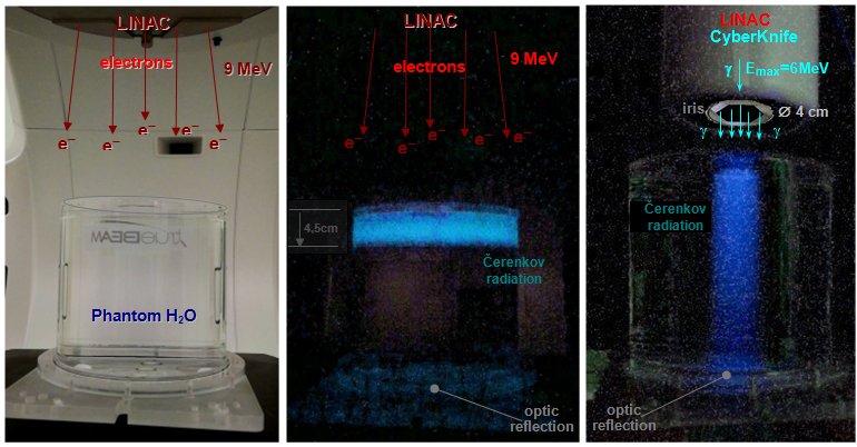 |
Cherenkov radiation generated in an
aqueous phantom during irradiation with electron and
photon radiation beams.
Left: A cylindrical phantom (diameter 20 cm and height 18 cm) filled
with water was irradiated with a wide (magnetically
scattered) beam of 9MeV energy electrons from a
linear accelerator.
Middle: During passing through the upper
part of the phantom, fast electrons generated Cherenkov
radiation to a depth of about 4.5 cm, when the energy of
the electrons fell below the threshold level of 260 keV.
Right: When irradiating the same phantom
with a beam of photon radiation (max.
energy 6MeV, beam with a diameter of 4cm) secondary
electrons along the g beam
form Cherenkov radiation - with a deep decrease in
intensity as the primary photon beam weakens as it passes
through water (just below the surface, a
slight increase in intensity is initially seen - build-up
effect to a depth of about 1 cm, discussed below) "Secondary radiation generated by X and g interactions").
Note: In the upper and lower part, optical
reflections of light from the cover and from the bottom
of the phantom are visible. Due to the relatively weaker
intensity of the images, the images contain a higher
amount of disturbing noise...
Acknowledgments: Irradiation of
the water phantom on TrueBeam and CyberKnife
devices was performed in cooperation with colleagues:
Ing.L.Knybel, Ing.L.Molenda and Ing.B.Otáhal. |
Display of radiation beams
in a liquid scintillator
Another option for displaying the passage of beams of ionizing
radiation through a substance in a suitable phantom is the use of
a liquid scintillator (liquid
scintillators and their use for internal measurement of
beta-radioactive samples are discussed in §2.6, section "Detection of beta radiation by liquid
scintillators").
At our department, we used a liquid
scintillator (in a very unconventional way)
to map and visualize the radiation
beams - electron, photon, proton - used in radiotherapy.
We filled a glass measuring cylinder with a
diameter of 6 cm and a height of 44 cm with 1 liter of liquid
scintillator (we used dioxane
scintillator with a density of 0.95 g/ml) and
placed it under the irradiation head of the respective irradiator
- electron Varian, photon CyberKnife, proton IBA.
From the side, we observed and photographed the
scintillation radiation generated in the scintillator along the
passage of the irradiation beam :
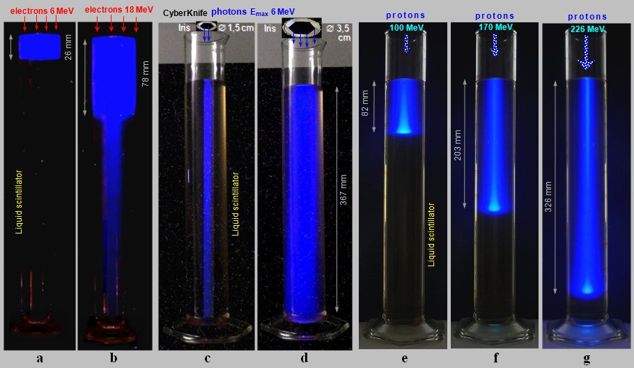 |
Scintillation radiation generated in a
cylinder (diameter 6 cm and height 44 cm)
filled with a liquid scintillator during irradiation with
electron, photon and proton radiation beams.
a), b): A cylindrical phantom
filled with a liquid scintillator was irradiated with a
wide electron beam of 6 MeV and 18 MeV from a linear
accelerator.
c), d): When irradiating the same phantom
with a photon beam - max. energy 6MeV,
beam 1.5 cm and 3.5 cm in diameter - secondary
electrons along the g beam
generate scintillation radiation - with a deep decrease
in intensity, as the primary photon beam weakens when
passing through a liquid.
Acknowledgments: Irradiation of
the scintillation phantom on TrueBeam and
CyberKnife devices was performed in cooperation with
colleagues: Ing.L.Knybel, Ing.L.Molenda and
Ing.B.Otáhal.
e), f), g): When
irradiated with narrow ("pencil
beam") proton beams of energy 100, 170
and 226 MeV, the protons penetrate to different depths
depending on the energy, with a prounced Bragg maximum.
Acknowledgments: Irradiation with
proton beams from the IBA cyclotron was performed in
cooperation with colleagues: Ing.P.Máca,Ing.M.Andrlík,Mgr.L.Zámeèník, Ph.D. , Ing.M.Navrátil, Ph.D. (and consultations with colleagues
Ing.V.Vondráèek and MUDr. J.Kubeš, Ph.D.) from the PTC proton center. |
Analysis and
discussion of the images :
¨ When irradiated with a wide
electron beam of energy 6MeV (a),
a bright blue glowing trace to a depth of about 26 mm can be seen
in the scintillator, where the electrons are already braked.
¨ Electrons of energy
18MeV (b) continue to a depth of about
78mm, while scintillation radiate. However, the interaction of
these high-energy electrons with the scintillator atoms also
produces intense photon braking radiation, which
is penetrating and continues to depth.
The angular distribution of the emitted
photons of braking radiation depends on the energy of the primary
charged particles. At low energies, the braking radiation is
emitted practically isotropically in all directions from the
point of interaction. As the energy of the electrons exciting the
braking radiation increases, the mean angle of the emitted quanta
becomes smaller and smaller - at high energies of the incident
charged particles, the braking radiation is preferentially
emitted in a narrow cone "forward"
in the direction of impact of the primary particles. The
directional radiation pattern of high-energy braking radiation
has the shape of a sharp "lobe" in the direction of the
primary beam.
Thus, in addition to a clear scintillation pattern of electrons
in the upper part, we also observe a weaker narrow beam
of braking radiation, continuing to the bottom of the
phantom.
¨ When
irradiated with a photon beam from CyberKnife
(narrow and wide - c, d ) with a continuous
spectrum with a maximum energy of 6MeV, we see a
significant scintillation trace from secondary electrons across
the entire cylinder - the photon beam penetrates deep
to the bottom (and would reach even deeper), with a slight depth drop in intensity as the photons
are gradually absorbed as they pass through the liquid.
It is interesting to compare these images
with the above representation of the same irradiation beams using
Cherenkov radiation in an aqueous phantom.
¨ When irradiated with proton
beams (e, f, g), we see a significant
scintillation trail, which amplifies and ends
with a bright Bragg maximum; the radiation no
longer continues to a greater depth. The depth
of the Bragg maximum increases with proton energy.
The blue "halo"
around the proton beam is caused by secondary electrons ejected
from the matter as the protons pass. With lower proton energy,
this "halo" is wider - electrons are less collimated in
the direction of the primary beam; this is especially evident at
the end of the trajectory around the Bragg peak, where the
protons are already considerably slowed down.
Irradiation
field
From a geometric point of view, radiation for radiotherapy can be
divided into one or more areas of certain shapes and intensities
and from different directions - the so-called irradiation fields.
For surface lesions, one irradiation field of softer photon
radiation (or electrons) is usually sufficient; for lesions
deposited in depth, a larger number of suitably shaped
irradiation fields are used (converging or
opposite fields, "crossfire" of four fields and many
other combinations). Various absorption
filters, screens, wedges (Fig. 3.6.1b ') or special collimators (see below) are often used to
form the shape of the radiation beam (and thus also the isodose curves),
suitable filters are used to influence the
energy spectrum of the radiation. To compensate
for the irregular shape of the surface, or to adjust the dose on
the surface and in depth, the so-called compensatory
bolus (Greek bolos = lump,
wad, piece ) is sometimes used - a
suitably shaped tissue-equivalent material of a certain
thickness, which is applied to a suitable place on skin, or
inserted off-surface into the radiation beam.
Note: A more
detailed description of irradiation techniques of this kind lies
outside the scope of our physical treatise. From a physical point
of view, they are not very interesting and, moreover, they are
gradually being pushed out more and more by more advanced and
accurate IMRT and IGRT techniques - see below.
The most perfect deep irradiation
technique is isocentric irradiation with
high-energy radiation with suitable shaping and modulation
of the irradiation beam - IMRT,
with possible imaging navigation IGRT - and stereotactic
irradiation with narrow sharply collimated beams of
radiation (with radiation navigation); the most complicated is hadron
radiotherapy. These methods are successively described
in detail below.
Isocentric
radiotherapy
The main strategic goal of radiotherapy - effective selective
irradiation of the tumor loci with the least possible
damage to surrounding tissues - is achieved by irradiating the
tumor site with a collimated beam from multiple
directions *) so that the intersection of beams,
ie focus or isocenter, where
doses add up, it was localized to the tumor site - Fig.3.6.1a.
The surrounding healthy tissues then receive a reasonably lower
dose, divided into a larger region. Simply put, healthy
tissue (its individual sites) is irradiated only once, while the
tumor is irradiated each time.
*) For this purpose, the radiator is
mounted on a special round stand, the so-called gantry
(gantry - portal, continuous supporting structure ),
enabling controlled rotation of the radiation
source around the patient by means of electric motors.
Fig.3.6.1. Movement isocentric radiotherapy with a
collimated beam of gamma radiation.
a) Basic idea scheme of radiotherapy with a
rotating irradiator. b) Arrangement of the
irradiator with a linear accelerator. c) Example
of a modern IGRT irradiator.
Collimated
fields and radiation beams for radiotherapy
From a general physical point of view, the properties of ionizing
radiation were described in §1.6 "Ionizing radiation" (fields and beams were then mentioned in the section
"Fields and beam, radiation
intensity"). The primary radiation from the accelerator (electron
radiation or proton radiation for hadron therapy) usually emits
in a precisely defined direction, in a narrow beam (which is then
further modified, filtered and shaped). However, the radiation g (and possibly X),
arising in radionuclides (cesium or cobalt), or excited as
secondary braking radiation after the impact of the primary
electron beam from the accelerator on the target (Fig.3.6.1b), is
emitted in practically all directions (high-energy
braking radiation has only a higher intensity in the central
direction, which is corrected by a homogenization filter). In order to create an irradiation beam for targeted
(tele)radiotherapy, it is necessary to shield
the vast majority of this diffuse radiation and transmit only the
radiation in the required direction - to perform the collimation
of the radiation. The simplest collimation is roughly
shown in Fig.3.6.1a - tube-shaped collimator.
More complex collimation systems are used to accurately shape the
irradiation beam, the most advanced of which are the
electronically formable MLC collimators
described below ("Irradiation beam
modulation").
In the middle part of the
(homogenized) beam of radiation defined by the collimator, there
is an approximately homogeneous intensity distribution. At the
edges, the intensity does not suddenly decrease to zero, as would
follow from an idealized geometric configuration, but decreases
continuously. Absolutely sharp collimation cannot be achieved in
practice for two reasons :
- Geometric
blurring due to the non-zero size of the primary source (manifests itself especially in radioisotope sources) .
- In
the case of penetrating high-energy radiation g, partial translucency
occurs trough the edges of the collimator .
In the marginal parts of the
collimated beam, a kind of "half shadow"
is created. Next to this geometric penumbra,
the scattering of the radiation beam in the
tissue also applies (this scattering is
significant especially in the electron beam).
At higher energies, the photon beam in the tissue is sharper,
there is less scattering penumbra.
These two effects - geometric and scattering - create in the dose
distribution in the tissue the resulting dose
half-shadow in the marginal parts of the radiation
beam, which must be taken into account when planning
radiotherapy, can significantly affect the isodose curves.
Technical note:
For the sake of simplicity, the irradiation beams are shown
in Figures 3.6.1 and 3.6.2d by lines (arrows) of constant width.
In reality, however, the radiation beams have a diverging
geometry - with distance from the radiation source are expanding
.
Radiotherapy planning
The combination of physical and biological factors in most cases
enables sufficiently effective and selective
irradiation of the pathological lesion. In clinical radiotherapy,
the patient's own irradiation is always preceded by a very
important and demanding process of radiotherapy planning,
the result of which is the so-called irradiation plan,
containing all the specific details of the irradiation process
for the patient. A properly designed radiation plan is a basic
prerequisite for successful radiotherapy.
The main basis for creating an
irradiation plan are detailed diagnostic images
of the irradiated area. At present, it is mainly the tomographic
X-ray images (CT), or on
nuclear magnetic resonance (MRI) and scintigraphy imaging, in
particular positron emission tomography (PET). These images serve both for the precise
localization of the tumor site together with the
determination of its size and shape, as well as a detailed
anatomical-density map of the distribution of tissue
densities and the location of organs.
Radiotherapy
simulator
In exact radiotherapy planning, a so-called simulator
is used - a device that mimics the entire irradiation process and
allows its optimization. The classic simulator is a diagnostic X-ray
device with an image intensifier, the X-ray tube of
which is mounted on a rotating isocentric arm and is equipped
with a system of adjustable apertures, enabling the imitation of
a beam of radiation as it will then be used on its own
therapeutic irradiator. The simulator enables localization
of the target volume and topometry of tumor deposits, aiming
of the beam and modeling of field geometry
and irradiation parameters, drawing of orientation and reference
points and markers on the patient's body.
Instead of the classic simulator, the
so-called virtual simulator - X-ray imaging
device CT is now often used for advanced
irradiation technologies (IMRT, IGRT), equipped with a aiming
system and special software for dose planning. The planning
software first converts the Hounsfield units of the CT image to
the electron density of the individual tissues.
Furthermore, the target volumes and critical
organs are marked on the pictures. Then the images are
overlaid with the characteristics of the radiation beams (energy,
dose distribution - isodose curves). The marked structures are
then displayed in the transformed BEV (Beam's
Eye View) mode - from the point of
view of the radiation beam. In conventional planning these
overlapping images are then sought to find the most favorable
irradiation conditions for delivering the desired dose to the
target volume. The number of irradiation fields and their shape,
dose rate, angles and other parameters for optimizing the
irradiation plan are set. The so-called inverse planning
will be mentioned below in connection with the IMRT and IGRT
techniques.
Images from CT examinations
are thus directly included in the planning of
therapy - 3D-planning, which is followed by the so-called 3D
conformal radiotherapy (3D CRT), or even more advanced therapy
with modulated IMRT-IGRT beams. The transfer of data from the CT,
via the planning computer to the computer controlling the
irradiator, provides the possibility of shaping the
irradiation fields based on accurate spatial knowledge
of the internal anatomy around the target tissue of the patient;
the radiation beams are thus adapted to the target volume and
protection of the surrounding critical tissues.
From these data and the
required radiation dose in the target tissue
(this dose depends on the tumor type - its radiosensitivity),
as well as the maximum tolerance dose in the surrounding critical
organs, the intensity, energy and geometric parameters of
the radiation beam are calculated, including precise radiation
positions and angles. Batch fractionation is further
determined . The whole process of planning and subsequent
radiotherapy is now largely automated using
computer software that works in several basic stages (Fig.3.6.2)
:
Fig.3.6.2. Some basic stages of computer radiotherapy planning.
a) Diagnostic X-ray (CT) image of the irradiated
area. b) Drawing of areas of interest of the
target volume and critical tissues, selection of the irradiation
procedure, number and shapes of beams (fields) and radiation
intensities. c) Optimization of the irradiation
plan using dose-volume histograms of DVH. d)
Control of the function and movements of the irradiator by the
resulting irradiation prescription.
l Analysis
of diagnostic data, choice of treatment strategy -
curative or palliative therapy, combination with surgery and
chemotherapy, localization of the target tumor volume.
l Processing of initial X-ray
images from CT (Fig.3.6.2a). Tissue density (expressed
on CT in Hounstfield units) is converted to electron
density. This takes into account the inhomogeneity of
the tissues (different electron densities of soft tissues, water,
air, bones) during the passage and interaction of the irradiation
beam. The electron density of the substance is directly
proportional to the linear energy transfer LET (the
amount of energy loss per unit path) and thus the local
ionization in the tissue and the absorption of radiation - radiation
dose distribution. To refine the irradiation plan, it is
also appropriate to take into account gammagraphic images of PET
(eg by computer fusion of CT+PET images), which map the viability
of tumor tissue - it was discussed above in the section "Diagnosis
of cancer".
l Drawing
the regions of interest ROI into the picture -
especially the target volume of the tumor
lesion, then the risk critical tissues and
organs (Fig.3.6.2b). These areas of interest are drawn in
individual transverse sections, the program combines them (using
interpolation) into a three-dimensional volume.
Perpendicular frontal and sagittal sections can also be used when
drawing ROI.
Target
volumes irradiation
Target irradiation volume (Target Volume TV) means the
corresponding region of tissue localization and size (volume), to
which must target canceroletal desired dose. For successful curative
radiotherapy, it is necessary to apply a lethal dose of
radiation not only to the actual volume of the macroscopically
detected tumor deposit, but also to some neighboring areas - the
so-called safety margins, reducing the
risk of insufficient irradiation of structures that could be
affected by cancer and subsequently cause recurrence of the
disease. In connection with this, we have three or four
consecutive target volumes in radiotherapy :
¨ Basic target volume GTV
(Gross Tumor Volume) represents the intrinsic volume of
a macroscopically detected tumor lesion, imaged using an
appropriate image (mostly CT). Some other neighboring areas - lem
- margin - are then added to this initial, basic or gross
volume .
¨ Clinical
target volume of CTV
To safely ensure local control of the irradiated
lesion, it is necessary to apply a lethal dose of radiation not
only to the actual volume of the macroscopically detected GTV
tumor site, but also to those neighboring areas where, according
clinical experience, microscopic spread of tumor cells could
already be hidden. Therefore, we increase the irradiated target
volume of GTV by a clinical safety margin - the
so-called clinical target volume of CTV
is created (Clinical Target Volume). It is analogous to
the safety margin in the surgical removal of visible tumors.
¨ Internal target volume of ITV
Due to internal physiological changes in the position of the
target volume within the organism (eg due to respiration *), variable filling of the
bladder and intestines, peristalsis, swallowing, heart
pulsation), further expansion to the internal target volume ITV
(Internal Target Volume) is needed, which
includes the entire pathway of internal movement of the target
tissue.
*) Tumor tracking
Advanced methods of stereotactic radiotherapy use the so-called tracking
of tumor - monitoring the movement of the tumor due to
respiration, its inclusion and correction, which allows to reduce
ITV and thus minimize the exposure of the surrounding
healthy tissue, possible escalate the dose to the tumor site
itself. These "tracking" methods of respiratory
gating or respiratory synchronization are discussed
below in the "Stereotactic Radiotherapy" section.
¨ Resulting planned target volume
of PTV
Due to the expected small deviations in the reproducibility of
the position of the patient and the irradiator during fractional
irradiation, it is sometimes necessary to further expand the
target volume by the so-called position edge. This
creates the resulting Planning Target Volume (PTV),
which is drawn in the irradiation plan. PTV includes the CTV and
an widening rim for ITV organ and tissue movement, as well as for
expected irregularities in irradiation settings. The resulting
PTV is thus a unification (outer envelope) of
all partial target volumes: PTV = GTV È
CTV È ITV È
[position edge].
l Entering
the required radiation dose in the target tissue and the
maximum allowable dose in critical tissues. This is based mainly
on empirical experience, which results in the coefficients a, b of radiosensitivity of
a given type of tumor tissue and tolerance doses for healthy
critical tissues (discussed above in the
section "Physical and radiobiological
factors"), passage "Prediction
of therapeutic effect").
l Selecting the
basic irradiation method - the number and
geometric configuration of the radiation fields, energy and
intensity of the beam - its eventual modulation, the number of
fractions.
l Calculation
of the distribution of local dose in the thus mapped
tissue - the so-called isodos curves are construct (illustratively is seen on Fig.3.6.2d). In practice, the radiation beam
is never homogeneous, as is the absorption of radiation in
tissue, so that the spatial distribution of radiation intensity
and the radiation dose is usually a complex form (highest dose is usually in the central part of the
beam, decreases towards the edges). The
spatial distribution of the radiation dose is often mapped using
the so-called isodose curves - imaginary lines
representing the connection of points with the same dose.
Usually, isodose curves are plotted for certain percentages from
the site with the maximum dose, e.g., isodoses of 80%, 50%, 20%,
and the like (reminiscent of contours on
the map).
l Optimization
of the irradiation plan. For this purpose, are often
constructed volume histograms of dose, so called Dose
Volume Histograms DVH
(Fig.3.2.6c). These histograms provide a plot of the 3-D dose
distribution using a illustrative 2-D curve display. Each marked
area of interest has its own DVH curve. On the horizontal axis is
the dose (in Gy or in % of the max. dose), on the vertical axis
is the volume (in % of the volume of the marked structure). DVHs
show the dose exposure of the target volume (PTV) and individual
identified critical organs (NT).
DVH
dose-volume histograms
Dose-volume histograms indicate, how much
of the volume of the target or critical tissue will receives a
particular dose. From the point of view of the basic radiotherapy
strategy, it is desirable that the largest possible volume of the
target (tumor) PTV tissue receives the highest possible
percentage of the required dose (ideally 100%). At the same time,
that the smallest possible volume of critical healthy tissue NT
received the lowest possible part of the dose. This dosage
exposure target volume and critical organs indicated
schematically shown in a dose-volume histogram DVH.
The optimization of radiotherapy here consists in optimizing
the areas under the DVH curves - the largest possible
area under the target PTV volume curve and the smallest possible
area under the histograms of NT critical organs (the proportions
of NT/PTV areas under the DVH curves represent the relative
"partial volumes" of irradiated NT tissues).
In a more detailed analysis, we
can further improve radiotherapy optimization by converting dose
and dose distribution values from standard DVH to quantities BED,
or to TCP + NTCP and derived UTCP
(these quantities were defined and discussed above in "Physical
and radiobiological factors in radiotherapy", passage "Prediction
of radiotherapeutic effect - TCP, NTCP").
l Data transfer to the irradiator coordinate
system .
l Creation of an irradiation prescription
, according to which the functions and movements
of the irradiator are controlled during the
actual irradiation (symbolically in Fig.3.6.2d) - mainly the
angular positions of the irradiator, exposure times, radiation
beam geometry using MLC collimator modulation.
Current planning computer
systems are also able to implement so-called inverse
planning (see below), in which the planning system
calculates the parameters and movements of the irradiator so as
to achieve the primarily required dose distribution in the target
volume (lesion) and do not exceed tolerance doses in surrounding
tissues.
Dosimetry
and verification in radiotherapy
In order to ensure the necessary accuracy of radiotherapy, verification
methods are also needed, ensuring the delivery of
correct therapeutic radiation doses to target lesions and
tolerance doses to at-risk critical tissues and organs, taking
into account changes in their position, anatomical shape and size
at different fractions of irradiation.
For dosimetric
verification, ionization chambers or diode detectors are
most often used. These detection elements can be individual (with
mechanical shift), in a linear or two-dimensional matrix
arrangement, or in a cylindrical structure for measuring
isocentric irradiation. They are placed in the irradiation beam
either directly ("in the air") to map the intensity of
the beam, or they are inserted into suitable water or plastic phantoms,
modeling typical anatomical structures for irradiation. Dose
monitoring is also performed "in vivo",
directly when irradiating a patient to whose body dosimeters are
applied to the appropriate sites. An elegant method of
verification and at the same time in vivo
dosimetry is the use of images from the portal
flat-panel of the irradiator (flat-panel
principle is described in §3.2, passage "Electronic display X-rays"), their calibration and
quantification - the so-called portal dosimetry
EPID (Electronic Portal Dosimetry image).
Rarely, 3-D gel
dosimetry systems are also used, allowing to determine
the spatial distribution of the dose in the irradiated volume
(the gel is filled into a phantom modeling the irradiated
structure). This method is quite demanding both in the stage of
phantom creation and in terms of evaluation (a more detailed
description is in §2.1, section "3-D gel dosimeters"), it is used only for research and development
work.
For the quantitative
assessment of the agreement of irradiation plans and dose
distributions, the so-called gamma-analysis is
sometines used, the output parameter of which is g -index
(0 <g£ 1); the closer the gamma value is 1, the better the
agreement.
In modern irradiation systems,
the irradiation and verification technology is integrated
into one irradiation device. High demands are placed on the accuracy
and reproducibility of the geometric
position of the patient relative to the radiation beam -
so that the irradiated target volume is precisely set in the
coordinate system of the irradiator. Various markers drawn or
placed on the surface of the body and laser sights
are used for this. Opposite the irradiator, detectors (display
flat-panels) are built into the gantry, enabling the creation of
so-called portal images during irradiation; even more
perfect is the X-ray system con-beam CT. These IGRT
-guided radiotherapy methods are described in the following
section "Modulation of
irradiation beams". In
classical stereotactic radiotherapy of
intracranial lesions, a stereotactic frame is used for
precise targeting of the target lesion, in cybernetic irradiators
special stereoscopic X-ray imaging and aiming systems -
see the section "Stereotactic
radiotherapy. Gamma-knife"
below.
The proper interplay of this
complex "technological chain" requires the cooperation
of an experienced radiological physicist.
Uncertainties in
radiotherapy
Every physical or technical, diagnostic and therapeutic method is
burdened with greater or lesser inaccuracies, errors,
uncertainties. Naturally, even during the complex chain of
radiotherapy, we encounter a number of uncertainties. The
"input" primary uncertainties are :
¨ Location
and extent of the disease , the uncertainty of which is
given by the accuracy and sensitivity of diagnostic methods,
event. it can be affected by artefacts of imaging methods,
inaccuracies in the patient's settings, his general movements and
the movements of organs inside the body.
¨ Radiobiological factors
- radiosensitivity of tumor and healthy tissues (parameters a, b in the LQ
model, the rate of cell repair and repopulation) is known only
approximately and on a flat-rate basis, and it can vary
considerably for individual patients. This leads to uncertainties
in the basic prescription of the radiation dose and its
fractionation.
During the process of planning and implementation of
radiotherapy, this is followed by other uncertainties :
¨ Inaccuracies in plotting ROI
- defining target volumes and critical structures in planning
images. This process is highly dependent on the experience of the
planing radiotherapist.
¨ Uncertainties in irradiation
technology - accuracy and stability of energy and
intensity of the primary irradiation beam, uncertainties in the
monitoring system, accuracy of the collimation system, geometric
setting of distances and isocenters, accuracy of transfer of
irradiation plan parameters to the irradiator control system.
¨ Inaccuracies
and disturbances during the patient's own irradiation -
variability in the positioning of patients under the irradiator,
fixation and movement of the patient, movement of tissues and
organs inside the patient during irradiation.
New knowledge in the field of
radiobiology, together with advances in diagnostic methods and
technical improvements in irradiation technologies, especially
their integration with imaging modalities, make it possible to
gradually reduce or eliminate these numerous uncertainties. This
increases the radiobiological, dosimetric, geometric and overall
accuracy of radiotherapy.
Modulation of irradiation beams
Radiotherapy with modulated beam intensity - IMRT
In order to perform sufficiently intense and
homogeneous irradiation of the tumor and to protect of
surrounding tissues, it is necessary to shape the beam
to achieve maximum irradiation of the target volume of the given
geometry (size and shape) and the dose in the surrounding
environment is reasonably lower, so that the surrounding tissues
and organs are obscured (shielded) - protected against radiation.
For this purpose, suitably shaped filters
(masking blocks of various shapes) and apertures
or collimators, defining the field size, are
inserted into the radiation beams. This was previously done
manually for each irradiation field and was very laborious (the workplace was equipped with a mechanical workshop,
where the covering blocks were cast, cut and machined). With technical development, therefore, more universal
mechanically movable apertures have been created. By dividing
these apertures into independently moving segments, a very
flexible multi-lamellar collimator MLC ( Multi
Leaf Collimator) was constructed, mounted on the output of
the photon beam of braking radiation from the accelerator -
Fig.3.6.3.
The invention of the MLC multi-leaf collimator,
which led to the introduction of IMRT modulated beam
intensity irradiation, marked a major revolution in
radiotherapy: it enabled high-precision specially targeted
irradiation of tumor lesions of various shapes and
sizes, with maximum protection of surrounding healthy tissues and
critical organs. And in a relatively easy and reproducible
way, without the laborious making of non-standard tools.
MLC collimators have a larger number of lamellae
(approx. 60-120 sheets) 5-10 cm thick, which can be moved
independently by means of small electric motors. This
makes it possible to create an opening of any shape
for the radiation beam, or several openings dividing the bundle
into several parts. The edges of the lamellae are suitably shaped
to mimic a diverging irradiation beam to reduce
"half-shadow". The entire collimator can be further
rotated. The small electric motors driving the slats are computer
controlled - the MLC collimator is electronically
formable.
Irradiation is performed from several directions, while
during irradiation with the help of electric motors the position
of individual lamellas of the collimator changes - the intensity
is modulated across the radiation beam and thus
the dose is regulated in individual parts of the
irradiated volume. The beam of radiation is as if divided into
individual rays with different intensities. By combining several
fields modulated in this way from different directions, a more
optimal dose distribution, selective irradiation of the target
tissue with better protection of the surrounding tissues and
critical organs (which is obscured by appropriate MLC shaping) is
achieved. This makes it possible to irradiate even irregular
tumors, with maximum protection of healthy tissues in the
vicinity of the tumor. The method is called IMRT
(Intensity Modulated Radio Therapy) - radiotherapy
with controlled (modulated) beam intensity. This is
ensured by the construction of special MLC collimators, which
modify - shape, modulate- radiation beam at the
output of the radiator (linear accelerator). Dose intensity
modulation is achieved by superposition of overlapping radiation
fields during rotation of the irradiator with different positions
of the MLC lamellae. The edges of the lamellae projectively
"copy" the shape of the irradiated target volume,
transmit an intense beam into the tumor bed and shield the
surrounding tissues and critical organs.
 |
Fig.3.6.3. Electronically controlled
collimators for precision radiotherapy with modulated
IMRT beam.
a) The multi-lamellar collimator MLC
with the help of motor-shifted shielding lamellae allows
to flexibly shape (modulate) the radiation beam from the
accelerator for radiotherapy with modulated beam IMRT. b)
InCise -MLC for precise flexible shaping of the radiation
beam on CyberKnife. c) Binary (bipolar)
MLC for tomotherapy. d) An iris
-collimator (above) with an electronically
(motorically) controlled aperture size can replace a
whole set of fixed collimators with circular holes (below)
of different diameters in the CyberKnife gamma-knife. |
From the point of view of time control, the modulation of the
IMRT irradiation beam can take place in two modes :
l Intermittent mode
(step-and-shoot), where the collimator lamellae are in
motion only during pauses between irradiations. The MLC
collimator forms the desired aperture, through which irradiation
is performed. Then the irradiation is stopped, the lamellae are
moved to the next position (or the collimator is turn slighly),
the angle changes to gantry and another dose of irradiation takes
place. It is actually an improved technique for a large number of
static fields.
l Continuous mode
(dynamic, sliding windows) - the collimator lamellas
move smoothly, relocate and modulate the beam into the desired
shape during irradiation. The movement of the collimator lamels
in synchronization with the continuous rotation of the collimator
and the entire irradiator on the gantry, is electronically
controlled by the appropriate software. According to the
irradiation plan, when the irradiator is rotated on the gantry
(gradually by up to 360°), the dose rate changes and thus
irradiation with the modulated beam takes place. This process is
sometimes referred to as Intensity Modulated Arc
Therapy (IMAT) - intensity-modulated angle
radiotherapy.
Another
improvement of this system is called AMCBT ( Arc-Modulated
Cone Beam Therapy) - angularly modulated therapy with
conical beams, or VMAT
(Volumetric Modulated Arc Therapy) - volume modulated arc therapy,
or RapidArc. It contains an irradiation beam controlled
by a modulated MLC collimator and a controlled rotation of the
irradiator around the patient. In some systems, the primary
intensity of the beam is also continuously modulated
by regulating the flow of electrons in a linear accelerator.
Controlled moving of the bed with patient, turning of the
collimator and angular shift of the irradiator gantry are also
possible.
The VMAT
technique therefore allows the dynamic change of
some parameters during irradiation: - The gantry can move at a
variable speed; - The position of the individual lamellae of the
MLC collimator is variable during rotation; - The collimator can
rotate. The dose and geometry of the beam is thus continuously
modulatable during the rotation of the radiator on the
gantry.
Thanks to another, angular-intensity
degree of freedom (a number of finely adjustable
irradiation beam angles with individually set beam shape and
intensity are available), the selectivity of the radiation dose
delivered to the target tissue is further improved and the irradiation
time is shortened. By modulating the dose rate during
irradiation, healthy tissues and critical organs are better
protected, the whole-body dose is reduced.
In
addition to the standard MLC collimator, two modifications are
used :
Micro-MLC
(mMLC) - a miniaturized multi-lamellar collimator for irradiation
with narrow sharply collimated beams in so-called stereotactic
radiotherapy (see below). It is mostly used as an
attachment mounted on a standard irradiation head with MLC for
radiotherapy with modulated IMRT beam
InCise
MLC for precise flexible shaping of the radiation beam
on the CyberKnife (Fig. 3.6.3b)..
Binary
or bipolar MLC (Binary MLC) - slot-shaped with a
plurality (64) of linearly arranged lamellae that open and close,
thereby modulating the irradiation beam in the plane of the
transverse section (Fig.3.6.3c). It is used in so-called tomotherapy
(see below, Fig.3.6.4a). The slats of binary MLCs are driven
electromagnetically or pneumatically, which achieves a very fast
response of opening and closing of slats (tenths of a second).
The method of
intensity modulated radiotherapy, analogous to IMRT, has recently
been introduced even in proton radiotherapy - the so-called IMPT
(Intensity Modulated Proton Radiotherapy), see "Hadron
Radiotherapy" below.
Image-guided
radiotherapy - IGRT
The high potential for accuracy,
flexibility and conformity of IMRT technology (as well
as gamma-knifes, see below) can only be used effectively
in co-production with a very precise method of verifying
the targeting of the irradiation beam to the target volume. Such
verification of the target volume can be performed by
displaying the area of the irradiated lesion and
surrounding structures before each irradiation or fraction,
followed by computer comparison with initial planning images,
evaluation and transfer of results to the irradiator coordinate
system. In this case, it is on-line navigation according
to the picture. According to the current images obtained
immediately before each individual irradiation, the position of
the patient and the targeting of the tumor site can be adjusted
as required. This achieves a precise setting
that is updated accordingly each day of treatment. Only after the
patient's position has been verified in this way, the own
irradiation is started.
Such
additions and improvements irradiation technology is referred to
as IGRT (Image-Guided Radiation Therapy)
- radiotherapy controlled (navigated)
by image *), controlling the patient's position
- target volume and surrounding structures - during the treatment
process using radiological imaging methods. It
combines the IMRT irradiation technique with the imaging
verification technique (Fig.3.6.1b, c). It allows the display of
the target volume and surrounding structures using a display
device connected to the irradiator. A simpler method is the
above-mentioned portal imaging (lower flat-panel in
Fig.3.6.1b, c), which displays bone structures well, but often
does not provide sufficient contrast for imaging soft tissues,
including the lesion itself.
*) IGRT is sometimes
considered in the narrower sense only as a verification
method ; however, see the section "Hybrid
integration of imaging and irradiation technologies"
below.
For
quality imaging, the irradiator can be further equipped with an
additional X-ray imaging system (sometimes
called In Room CT - CT in the irradiation
room, Synergy, or OBI - On-Board Imager
System - an imaging system mounted directly
on the irradiator), which is used to accurately control
the position of the patient and target tissue before irradiation;
it can be performed before each irradiation fraction. The OBI
imaging system is mounted on the irradiator gantry (linear
accelerator) perpendicular to the irradiator's central axis. The
X-ray imaging system rotates together with the gantry and is
positioned to have the same isocenter as the high-energy beam of
the irradiator. Prior to irradiation, an X-ray
planar or CT image is performed on the
irradiator with a widely collimated cone-beam CT, which
shines trough the patient and impinges on the opposite flat-panel
imaging (its principle is described in §3.2,
passage "Electronic X-ray imaging"). The X-ray tube and the detector rotate
around the patient on a common irradiator gantry. The resulting
current images are compared with planning reference
images- initial CT or planar images from the simulator
and, if necessary, appropriate position correction
or beam shape modification by collimator MLC; in case of larged
differences also changes in the irradiation plan, its
re-optimization. This allows the elimination of errors in
patient positioning between the individual irradiation factions,
or changes in the position and size of the target tissue and the
surrounding anatomical conditions during radiotherapy. X-ray
display provides up-to-date images of structures
and organs before the irradiation procedure and, based on them,
the accuracy of radiotherapy is optimized by
controlled IMRT. The new systems enable verification not only
between individual fractions, but also inter-fraction
CT imaging during the rotation of the irradiator with IMRT.
Very
precise localization of the tumor and surrounding structures
helps to improve the therapeutic ratio - to
irradiate the tumor site with a sufficiently high dose and to a
large extent eliminate the harmful radiobiological effect on the
surrounding healthy tissues and organs. In principle, ultrasound
imaging can also be used for IGRT, but the recognition of
structures in these images is more difficult and is practically
not used in teletherapy. Ultrasound navigation is used in some
methods of brachytherapy,
as described below and shown in Fig.3.6.7 on the right. A
perspective method of IGRT is navigation using nuclear magnetic
resonance MRI - a combination of LINAC+MRI
(described below in the passage "Hybrid integration of imaging and radiation
technologies"), which provides a better visualization of
the structures of especially soft tissues.
The IGRT
verification method is most often used in connection with
irradiators with a modulated IMRT beam according to Fig.3.6.1b, c
*), so it is IMRT + IGRT. On the IGRT image
navigation are further based the high-precision tomotherapy
and stereotactic
gamma-knife, Leksell, and especially cybernetic radiotherapy
methods, described below. IGRT can be supplemented by a system of
correction for respiratory movement, the
so-called Respiratory Motion Technology or Real-Time
Position Management ( RPM ), which allows
monitoring of the change in the position of the target volume
depending on the patient's respiratory cycle - this is used for
selective irradiation of the target volume only in selected part
of the respiratory cycle, so-called respiratory gating,
or when synchronizing the movements of the irradiator with the
brathing cycle (respiratory synchronization). All these
procedures are now integrated into the DART (Dynamic
Adaptive Radiotherapy) system, which makes it possible to
evaluate the results obtained during IGRT and, based on them, to operatively
adapt the parameters of the irradiation procedure so
that the dose distribution is optimal.
*) Occasionally was used the
integration of linear irradiator with a CT imaging in the CT-on-Rails
design. A CT scanner, mounted on rails, is installed in the
irradiation room together with the irradiator itself. In the
opposite end of the room, it can be used for basic CT imaging. On
the rails, the CT scanner can then be moved to the radiotherapy
position, where the deviations of the target volume and other
structures are checked in comparison with the planning images,
with subsequent correction of the patient's position. This system
has again been used in some new carbon-12 hadron radiotherapy
systems (see "Hadron
radiotherapy" below), where it is
problematic to mount an On-Board imaging system on very
robust and complicated gantry.
Adaptive radiotherapy guided by the
image IGRT - "daily" CT or MRI - is carried
out by two on-line procedures of reoptimization of the radiation
plan :
-->
Position adaptation (ATP) in which the plan
adaptation is performed according to the new current position
of the patient under the irradiator. The position of the
isocenter is updated and the original contours (ROI) can be
applied to the modified plan.
--> Shape
adaptation (ATS) based on new anatomy of target
tissue structures and surrounding organs. Reoptimization of the
radiation plan is performed by changing the shape and size of the
ROI (either automatically or adjusted by the radiation
oncologist).
Biologically
guided radiotherapy - BGRT
Anatomical and functional-biological multimodality imaging
methods are increasingly included in the irradiation process,
together with modeling of molecular-cell radiation response of
tumor and healthy tissue (molecular imaging, monitoring of
radiotherapeutic effect including early detection of apoptosis,
discussed above in section "Diagnosis of
cancer"). The sum of these approaches makes it possible
to gradually achieve "biologically guided" radiotherapy
BGRT (Biologically Guided Radiation Therapy),
adapted to individual conditions specific to the patient and
tissue - radiotherapy controlled (guided) by molecular
imaging.
This area mainly
includes the biologically targeted radioisotope therapy
by open emitters (discussed below), where the complex theranostic approach
discussed in §4.9, section "Combination of diagnostics and therapy -
theranostics" is being
developed.
Hybrid integration of imaging and
irradiation technologies
The accuracy of the localization of anatomical
structures in CT and NMRI imaging, as well as the targeting of
the isocentre in the irradiators, is already very high, approx. 1
millimeter. However, the use of this accuracy to actually target
the dose to the desired site may be hindered by variability
in patient position and organ mobility
within, as well as changes in their size and anatomical
proportions (see "Conformal radiotherapy"
below). It is therefore desirable to continuously on-line
monitor the position of the patient and internal
anatomical structures using an imaging system directly on the
irradiator. This creates images of organs and anatomical
structures in the irradiator coordinate system, to which the
modulated irradiation beam can respond in feedback by modifying
and correcting irradiation conditions to achieve the exact
desired dose distribution in the target volume and surrounding
tissues. Image-guided radiotherapy (IGRT ) and tomotherapy
therefore require the merging of the imaging and
irradiation device into a single hybrid system -
Fig.3.6.1c and Fig.3.6.4a, c. Before each irradiation, it
is then possible to take "daily images"
of the target tissue and surroundings, according to which it is
possible to perform a possible correction of the position,
operative update of the irradiation prescription, or correction
of the irradiation plan.
In
IGRT systems, hybrid combination [LINAC + CT] is
already standard. Hybrid combinations of irradiator with the nuclear
magnetic resonance NMRI imaging system are under
development (the NMRI principle has been described above - "Nuclear magnetic
resonance"). From this combination is expected to better
visualiza the structures (target tumor as well as surrounding
tissues and critical organs) - especially soft tissues - on NMRI,
which would allow to make a more perfect adjustment and targeting
of the radiation dose from the irradiator. It is therefore a
two-mode MR-IGRT technology. The system has
already been tested [60Co
+ NMRI] - two or three cobalt irradiators (equipped with
MLC collimators) combined with simultaneous magnetic resonance
imaging. For the highly desirable combination [LINAC +
NMRI], a significant technical problem so far is the
mutual negative influence of both modalities - influencing the
operation of a linear accelerator by a strong magnetic field of a
NMRI superconducting electromagnet and interfering with NMRI
display by strong electromagnetic signals generated during
accelerator operation.
The radiation dose in the tissue - both desired and unwanted - is
caused by fast secondary electrons, generated in the tissue by
the interaction of primary photon (X, gamma) radiation. In a
strong magnetic field, these fast electrons will have their paths
deviated from their original direction - the Lorentz force acts
on them in the direction perpendicular to the motion and
perpendicular to the transverse magnetic field. This can alter
the resulting radiation effect of the irradiation beam. In dense
and homogeneous tissues, this effect is relatively small (electrons brake quickly in the tissue on a short path),
but at the interfaces between substances with different
densities, they can manifest themselves. Significant changes in
the dose distribution can occur especially at the air-tissue
interfaces - the so-called electron return effect
occurs here. Fast electrons that have already left the tissue at
the interface are no longer slowed down in the air, they spirally
bend in the magnetic field and can return back to the tissue;
this increases the dose at the interface.
Several
structural solutions of the LINAC/MRI combination with different
shaping of the electromagnets, perpendicular or longitudinal
orientation of the magnetic field and radiation beam, different
positions or rotation of the patient were experimentally built.
These prototypes were mostly quite complicated, suboptimal for
clinical practice and did not achieve full online connection of
the irradiator with MRI navigation. In the end, the most feasible
solution turned out to be the simplest in principle: to place
another ring gantry on the outside of the superconducting
solenoid, with the help of which the LINAC (with a target) would
rotate, which would inwardly irradiate the patient lying inside
the MRI tunnel :
 |
A simplified diagram of the hybrid
combination of a linear accelerator (LINAC) with magnetic
resonance imaging (MRI) - IGRT with nuclear magnetic
resonance navigation.
(Note: There is only one LINAC; two are drawn in
the picture only to illustrate the different position
when the gantry rotates) |
With special methods of active magnetic and electromagnetic
shielding, mutual interference can be minimized and both
modalities can work independently and simultaneously. Other
effects (such as changes in dose distribution due
to the magnetic field) can be corrected in software and
included in the radiation plan. Thus, it was possible to realize
a functional hybrid LINAC/MRI combination. Two
types of devices of this kind were developed and began to be used
clinically :
-
MRIdian from the manufacturer ViewRay
Technologies (MRI 0.35 T + Linac 6 MeV), completed in 2014 (previously this manufacturer supplied the
aforementioned 60Co+MRI, later replaced cobalt with a linear
accelerator).
- MR-Linac Unity,
which was developed in the years 2012-18 in cooperation between
the manufacturers Electa (manufactured Linac 7 MeV) and Philips
(MRI 1.5 T).
Navigation
of adaptive radiotherapy by magnetic resonance MRI is undoubtedly
a very interesting method from both a physical and a clinical
point of view. It is legitimately assumed (at
least hypothetically...) that it can significantly
contribute to the precision and better success of
radiotherapy, especially in situations of complex anatomy
of soft tissues, where the irradiated tumor tissue is closely
adjacent to at-risk critical tissues and organs. Moreover, these
anatomical structures often move relative to each other
during the radiotherapy process, changing shape and size. These
soft tissues - target and surrounding healthy - tend to be difficult
to visualize using conventional cone-beam CT
navigation on the irradiator. However, they are shown with excellent
contrast on MRI images and can be focused and contoured even
without the use of fiducial markers. It is mainly for tumors of
the pancreas, prostate, rectum, ... In general, however, MRI
navigation of radiotherapy is expensive, laborious and
time-consuming. And the spectrum of suitable diagnoses is
quite narrow. It is necessary to assess in which cases this time
and effort is justified and necessary. So far there is only
limited evidence of its actual better efficacy and
superiority..?..
The
scintigraphic method of PET positron emission tomography
is very suitable for primary tumor diagnosis (see Chapter 4
"Scintigraphy", part "PET cameras"),
especially with the use of radiopharmaceutical 18FDG.
The metabolic cellular activity of the tissues is displayed.
However, this method is also suitable for monitoring the
response tumor tissue for radiotherapy, as it displays
metabolically active tumor tissue, as opposed to inactivated
cells. Among other things, it is able to recognize tumor
recurrence from other processes (eg from the consequences of
previous tumor treatment). This monitoring of the success of
radiotherapy can be performed off-line, but a hybrid combination
of [LINAC + PET] radiotherapy irradiator with
PET imaging is also possible.
Another
interesting hybrid combination that may be implemented in the
future is the combination [hadron 12C-irradiator
+ PET], where the dose distribution from accelerated
carbon core beams is monitored by annular positron emission
tomography (PET) camera detectors displaying annihilation photons
generated in areas of Bragg maxima from positrons b+
-radioactive 11C - see below
"Hadron
radiotherapy", passage "Radiotherapy
with heavier ions", fig.3.6.6. And in the distant
future a possible hybrid combination [antiproton
irradiator + PET], where a PET camera mounted on
antiproton irradiator gantry could monitor the dose distribution
in the tissue by detecting annihilation radiation from positrons
arising secondarily from antiproton interactions in the tissue
(see "Antiproton radiotherapy" below).
Conforming, adaptive radiotherapy.
Inverse planning.
All these gradually evolving methods
lead to better irradiation selectivity - a
higher dose in the target tissue and a reduction in the
dose to the surrounding healthy tissues. They allow better dose
distribution in the target volume - so-called conformal
radiotherapy (conform = adapt), also referred
to as three-dimensional conformal radiotherapy (3DCRT).
In this technique, a three-dimensionally defined target volume is
selectively and homogeneously irradiated with the desired high
radiation dose, which drops sharply outside the target volume, so
that the surrounding healthy tissues are irradiated with a
substantially lower dose. The size and shape of the irradiated
area is adapted to the irregular volume of the tumor
lesion. The dose distribution can be adapted for tumor foci of
various shapes, including the situation where the tumor foci are
closely adjacent, or partially surrounds critical organs and
tissues. IMRT uses a number of irradiation fields at different
angles, which adapt to the shape of the lesion and
"copy" its contour. The modulation of the irradiation
beam makes it possible even to partially cover it
certain parts of the target volume, that interfere with a
critical organ, on which the tumor may push (or partially
surround it). The radiation dose in the target tissue is then
compensated by stronger irradiation from other fields. As a
result, sufficient and almost homogeneous irradiation of the
tumor site can be achieved with significant protection of
adjacent critical organs (isodose curves can be concavely
"curved" around the critical organ). This result is
achieved in IMRT by inhomogeneous transport of partial radiation
doses to the lesion, adapted to the irregular shape of the tumor
and the anatomical situation in the environment.
Conformal
radiotherapy techniques make it possible to selectively
increase (escalate) applied radiation doses in target
tissue by reducing the dose in critical organs. The sum of these
IMRT + IGRT methods is also sometimes called adaptive
radiotherapy (ART) - irradiation is adapted
to each patient individually, it changes with specific anatomical
conditions, even over time in the same patient *). Operative
continuous IGRT includes, in addition to the three
dimensions of spatial imaging, even a time
factor - sometimes referred to as 4D-radiotherapy.
*) The irradiated patient is
not immobile and unchangeable object! There are a number
of events that can change the patient's internal anatomical
proportions somewhat. Respiratory movements, intestinal
peristalsis, changes in tissue volumes due to the dynamics of the
disease and due to the therapy itself take place. This can lead
to differences in the position of target volumes of up to units
of centimeters. This can have a significant effect on the
accuracy of selective radiotherapy; without correction for these
facts, the target lesion could be partially "missed"
during irradiation and healthy tissue could be irradiated
instead..!..
Correction for respiratory movements
is especially important when irradiating tumors in the lungs and
chest area. There are basically two modifications of the method
for eliminating the disturbing effect of respiratory movements on
irradiation :
- Respiratory gating , when the
irradiation beam is switched off and on so that the irradiation
takes place only in the selected defined phase of the respiratory
cycle (eg in the expirium period).
- Tumor tracking , where the scanned
breathing movements are electronically transmitted via a computer
to the irradiator control system, which "shifts" the
beam in the rhythm of the breath so that it is still directed to
the target lesion - respiratory synchronizitaion.
Said
complex method of radiotherapy planning, where the initial
requirement is the distribution of radiation dose and
computerized planning system determines the optimal shapes,
intensity and irradiation time of each modulated radiation
fields, sometimes referred to as "inverse
planning" :
Inverse Planning
The name "inverse" comes from the fact that some stages
are "reversed" here, compared to earlier conventional
planning procedures (conventional planning is
sometimes referred to as "forward").
First, the target volumes and structures of critical tissues and
organs on individual CT sections are accurately marked. After
entering the required dose into the target tissue and the maximum
permissible dose for the surrounding healthy tissues and critical
organs, a 3D-model of the dose is created. The
planning system then designs the number and shape of the
irradiation fields, the dose rates, the times, the angles of the
gantry irradiator; this was previously done manually in
conventional planning. Each partial radiation field (from a given
angle) is virtually decomposed into individual surface elements -
pixels, the distribution of which is controlled by the
positions of the lamellae of the multi - leaf collimator MLC;
this distribution is computer-optimized so that the spatial
distribution of the dose corresponds to the required values. An
important output part of the computer irradiation plan is
therefore the data on the position of the lamellae and the angle
of rotation of the MLC collimator. All this data is transferred
to the irradiation computer, which according to them electronically
controls all movements of the gantry, collimator leafs,
accelerator power and other irradiation parameters. The adjective
"inverse" is likely to become unnecessary in
the future, as no other type of planning will exist ...
Besides to the high
purchase price (and higher operating costs), a certain disadvantage
of all these advanced radiotherapy methods is greater
time-consuming irradiation process and a somewhat higher
whole-body dose of radiation (even outside the directly
irradiated area), arising as a result of more frequent
diagnostic and monitoring irradiation.
Paradoxical
note: Accurate irradiation of a defined tumor site with a
rapid decrease in the radiation dose to the environment is
certainly very desirable and leads to a better protection of
healthy surrounding tissues. On the other hand, it can sometimes
paradoxically have a certain disadvantage: in the case of
micro-seeding of tumor cells into the vicinity of the defined
lesion, recurrence of the disease may occur more easily after the
end of radiotherapy than with earlier methods, where the
surroundings of the target volume was relatively strongly
irradiated. It is therefore necessary to pay increased attention
to the definition of a sufficient area of the envelope around the
lesion itself and its incorporation into the target volume.
Tomotherapy
A special modern variant of IGRT-radiotherapy navigated by CT
images is the so-called tomoradiotherapy. The prefix "tomo" expresses the fact
that the irradiation takes place gradually in a series of narrow
transverse sections perpendicular to the
longitudinal axis of the patient, defined by a beam from the
orbiting accelerator (Fig.3.6.4a).
Diagnostic imaging and therapeutic irradiation technology is
integrated into one system. CT imaging provides
up-to-date images of the target tissue and surrounding
structures before each irradiation procedure ("daily CT")
and, based on them, optimizes the
positions and accuracy of radoiotherapy with controlled
modulation of the beam intensity.
An
interesting variant of the tomotherapeutic apparatus was
realized, using the same linear accelerator as a source of
radiation for imaging and for therapeutic irradiation :
¨ CT
imaging is realized as a transmission g
-CT, where instead of the X-ray tube there is a linear
accelerator with a target, producing in the "low
dose" mode (with reduced energy and especially with
many times lower beam intensity) photon radiation
("megavolt X-radiation") fan-shaped collimated
("Cone Beam"), which shines trough the
patient and is registered in the opposite direction by a set
of detectors (arranged in a circular section, most often
it is a multipixel single-row xenon ionization chamber, more
recently scintillation detectors with ceramic materials) similar
to classical CT. As with CT diagnostics, along with the rotation
of the accelerator and detectors, the bed is moved
with the patient (helical or spiral scanning), followed by the
reconstruction of the density images.
¨ The same linear accelerator, after
switching to high-dose power mode (without
using a homogenization filter), orbits
around the patient and irradiates the target
tissue localized in the previous diagnostic CT step. This
irradiation takes place with a modulated beam
using an MLC collimator *): for different angles, the intensity
of the g-beam can be greater or less
(or radiation completely switched off), or the beam suitably
shaped so that the radiation dose avoids critical tissues. As in
the previous step, together with the orbiting of the accelerator
and detectors, the bed and the patient are moved in a controlled
manner - helical or spiral tomotherapy is
performed. Modulation of the dose intensity is achieved by
superposition during the rotation of the irradiator with
different positions of the lamellae of the binary MLC, modulation
in the longitudinal direction then by means of superposition
during the overlap of the individual sections.
*) Since tomotherapeutic irradiation
takes place only in a narrow beam rotating in a plane
perpendicular to the translation axis, it is sufficient to
modulate the irradiation beam intensively only in one direction
(plane). Therefore, a special somewhat simpler multi-lamellar
collimator MLC is used here, sometimes called binary
(bipolar) MLC, which, however, has a faster opening
and closing response of the lamelae (Fig.3.6.3c). It typically
consists of 64 slats with a pneumatic drive mechanism.
During
high-performance irradiation, CT detectors must be switched off
or removed, as high radiation flux would overwhelm them and could
damage them (in further development, the detectors are expected
to be switched on even during irradiation and to continuously
modulate feedback intensity). This elegant, accurate, and highly
integrated system is sometimes referred to as "HI-ART"
("Highly Integrated Adaptive Radiation Therapy").
The first prototype
of a tomotherapeutic irradiator (Corvus system) were
constructed in 1993 by M.Carol (Nomos Corp.), T.R.Mackie,
P.Reckwerdt et al. (Univ. of Wisconsin). For further development
and production of these devices, the company Tomotherapy
Inc. was founded in 2002 based in Madison, Wisconsin, USA, which
supplies these systems commercially. It later merged with Accuray,
a company that produces CyberKnife.
Tomotherapy with 60Co
In principle, a radionuclide emitter 60-cobalt (g 1173 + 1322 keV)
can be used as a source of photon radiation for tomotherapy, as a
replacement for LINAC (as discussed above in the
section "External irradiation with
gamma, X and electron radiation - teleradiotherapy", dose distribution for g- radiation 60Co is very similar to
LINAC 4 or 6MeV). The classic cobalt irradiator, for this
purpose, is equipped with a binary multi-leaf collimator and an
opposite imaging detector (flat-panel). It can operate in the
same configuration as in Fig.3.6.4a, or using two or three 60Co sources - one for flat-panel
imaging ("daily CT"), the other for self-therapy.
However, such systems are used only very rarely, because
radionuclide sources in teleradiotherapy are generally abandoned
(with the exception of Leksell's gamma knife).

Fig.3.6.4. Some special gamma irradiation techniques (top
principle, bottom device). a) Tomotherapy. b)
Lexell's gamma knife. c) Cybernetic gamma-knife.
Stereotactic
radiotherapy - SBRT. Gamma - knife.
Stereotactic Body Radio Therapy (SBRT )
is a very accurate high-dose irradiation of a
small target volume, usually a large number of targeted thin
beams of intense ionizing radiation, with a sharp
decrease in radiation dose outside the target volume (sometimes referred to as the "zone effect"). Each individual beam is relatively weak and does not
cause significant radiobiological effects on its tissue path.
However, if these rays are directed to a common focus
- target tissues, their summation results in a high effective
dose capable of damaging and inactivating tumor cells. Outside
the focus, the radiation dose decreases sharply, so that already
at a distance of a few millimeters from the focus, the dose
already corresponds practically to the dose from one beam. Using
the so-called stereotactic targeting, the target
volume is precisely spatially defined by transferring the
diagnostic image to a 3-dimensional coordinate system
(without direct visual inspection). Based on the coordinates that
locate given places, it is possible to achieve highly selective
irradiation of even a small target deposit with a high dose of
radiation, with relatively low damage to surrounding tissues. Due
to its high accuracy, the method is sometimes referred to as stereotactic
radiosurgery SRS (Sterotactic RadioSurgery) *)
- allows a single-time ablation irradiation with
a high dose, which eliminates the lesion (tumor or malformation).
This method is suitable where classical surgery is difficult or
unsolvable (eg fine structures in the brain). This targeted
irradiation with a "gamma-knife" can then be a
non-invasive alternative to surgical resection - without surgical
burden and surgical complications (bleeding, infection). High
accuracy (1-2 mm) enables effective treatment of even small
tumors near important centers or in areas with a complex
anatomical structure. Irradiation is usually performed once
or with a small number of fractions (2-3).
*) After all, this method is used not only
for cancer therapy, but also for "radiosurgery"
removal of vascular malformations or neuropathological (eg
epileptic) foci in the brain - disposable focal
intracranial irradiation. Stereotactic radiosurgery is a
non-invasive alternative to "bloody" surgery.
Terminological note: The
term stereotaxy was created by combining the
words: stereo = spatial and taxe= intervention in
the right place (Lat. tactio = touch). It is also
used for accurate surgical procedures.
In classical
radiotherapy, standard single doses of about 2 Gy are
applied in 20-40 fractions, the radiobiological mechanism is cell
apoptosis with the aim to reproductive
sterilization of clonogenic tumor cells; the resulting
effect is described by the LQ model. In stereotactic
radiotherapy, a high single dose (in the order of tens
of Gy) is applied to a small target lesion either one-time or in
a few fractions (1-5 fractions). With a one-time dose of tens of
Gy, in addition to apoptosis, immediate cell death
in interphase - necrosis is already partially manifested
(radiobiological effect is no longer
precisely described by the LQ model, its high-dose modifications
are sometimes used - LQL model, gLQ model, USC
(universal survival curve), KN (Kavahagh-Newman) model, PLQ
(Padé Linear Quadratic), see §5.2, passage "Deviations from the LQ model and its
modifications". Tumor cells are affected by such a large radiation
dose (with high dose rate), that nitrocellular repair will not
take place and cell repopulation not in progres (due to the short total treatment time), all cells are "killed" - the tumor
sterilization effect becomes ablative.
Therefore, in addition to the name stereotactic radiotherapy
SBRT, the term stereotactic ablative radiotherapy SABR,
SABRT (Stereotactic Ablative Body
RadioTherapy) is also used; sometimes,
with a bit of exaggeration, the association with the English word
"saber" is mentioned - it is an effective and
elegant weapon against tumors... It is
interesting to note, that at the high-dose SABRT is more
pronounced the abscopic effect (otherwise rare)
of the anti-tumor immune response (§5.2,
passage "Bystander-Abscopal effect").
Stereotactic radiotherapy
makes it possible to precisely target a high radiation dose to
the tumor focus, while maximally saving healthy tissues. This can
achieve high local control - effective destruction of the
tumor lesion - even near important critical organs and
complex anatomical structures, with a lower risk of side effects
and complications (lower radiotoxicity,
less risk of secondary radiation-induced malignancies). Stereotactic irradiators - Lexell's gamma knife
and CyberKnife - irradiate with about 10-30 times higher
spatial accuracy than conventional linear accelerators.
Note: Similar
goals are achieved by somewhat different means - beams of
heavy particles - the Hadron
radiotherapy, below.
Leksell
Gamma-Knife
Now already classic device for high-precision isocentric
radiotherapy is Leksell Gamma-Knife LGK (first prototype developed in 1967 by neurosurgeon
L.Leksell and radiologist B.Larsson with coworkers at the
Karolinska Institute in Stocholm).
Radiotherapy takes place by precisely targeted irradiation of a
pathological site in the brain with gamma radiation from a large
number of solid radioactive sources 60Co (g 1.173 + 1.332
MeV), whose narrow collimated rays from different directions
intersect in a common focus, into which a
pathological district of brain tissue is positioned by
stereotactic localization. Large total radiation doses from all
intersecting rays act in the focus, outside this focus the dose
decreases sharply and is already 100 times smaller in the
vicinity of a few millimeters from the focus; corresponds to the
dose from a single beam. The emitters are arranged on a
hemispherical surface and are equipped with collimators,
that directs (transmits trough the channels) the beams of
radiation g to the center (Fig.3.6.4b above). In the basic type of
device there are 201 small encapsulated cobalt sources with
activities of about 1GBq, evenly distributed on a hemisphere with
a diameter of 400mm, which gives a dose rate of about 3 Gy/min.
in the isocenter.
Definitive precise collimation
is performed by secondary collimators in special collimation
helmets (there are several types of them in the
accessories of the instruments, or their segments can be moved by
motor). Prior to the actual radiotherapy, a coordinating stereotactic
aiming frame is attached to the patient's head with four
screws (Fig.3.6.4b below), enabling on the X-ray or MRI imags to
mark the position of the pathological lesion together with
contrast markers on the frame, and assign the displayed
structures to the three-dimensional coordinate system of the
irradiator. More preferred here is magnetic resonance imaging,
which provides a more contrast imaging of the soft tissues of
brain structures. The tomographic image of the brain, which also
shows the marks of the stereotactic frame ( fiducial markers),
is transferred to the planning system and serves to precisely set
the target volume to the focus of the gamma knife. Rays from some
60Co
sources can be discarded as needed (by a shielding
"plug" in the helmet), if they pass through critical
structures that should not be exposed to radiation (such as the optic nerve, ocular lens, brainstem). Irradiation time depends on the size and type of
lesion, it is on the order of tens of minutes. Tumors are
irradiated with a single dose of about 20-25 Gy, up to 100 Gy (necrotizing ablation dose) is
used in malformation radiosurgery. If the target volume is larger
or irregular in shape, the bed is moved with the patient so that
the focus moves in the lesion and there is a gradual irradiation
of the entire target volume - multi-isocentric
irradiation. Brain tumors for LKG therapy should not be larger
than 3 cm and their number should not be greater than 5. However,
in some workplaces 20 lesions are irradiated, mostly with
palliative intent. The therapy is basically one-time,
but in case of recurrence or appearance of new metastases, the
treatment is repeated, even 3 times.
Several
improvements have been made to the new Lexell gamma-knife types (Perfection, Icon) :
-> The irradiation
space has been enlarged (using 192 cobalt
radiators with cylindrical geometry, without collimator helmets -
these are replaced by a motor-controlled conical collimator with
8 independently moving segments with 576 holes), which, in
addition to brain lesions, allows irradiating other target
volumes in the head area and neck (up to the C1,
C2 vertebrae).
-> An additional imaging
rotary con-beam CT system was installed to enable reference
stereotactic imaging.
-> An additional
possibility of fixing the head using a thermoplastic mask
and a control infrared camera that monitors its
position, with reproducible settings at multiple fractions of
irradiation, was added.
The gamma
knife is used to treat mainly brain tumors and metastases,
meningiomas, auditory nerve neurinoma, ocular uveal melanoma,
vascular and neurological malformations, and pituitary adenoma.
Leksell's
g- knife has three disadvantages :
¨ Its construction is
basically single-purpose - adapted for the
therapy of brain lesions (the innovated model also
allows irradiation of lesions in the neck area) .
¨ Radioactive emitters 60Co have a half-life of 5.27 years,
they gradually weaken and need to be replaced.
This is a very complicated and expensive matter...
¨ An unpleasant and uncomfortable
aiming stereotactic frame attached to the head for the
patient (this fixation should not be used in young
children, whose skull is not yet quite strong).
Nevertheless,
Leksell's gamma-knife is intensively used in larger workplaces
specializing in diseases of the central nervous system. It is the
most accurate device for tumors in the head area.
Universal and cybernetic
gamma-knife
With the technical improvement of the "classic" IGRT
isocentric radiotherapy using g-
radiation, precise irradiation with narrow beams
with millimeter accuracy is also possible here. This gradually
achieves the properties of a gamma knife for universal
use, for various irradiated localizations, not just the
brain *). In addition to precisely working IGRT irradiators with
an MLC collimator, resp. mMLC (micro-multileaf collimator -
Fig.3.6.3b) - in the classical, VMAT, or tomotherapeutic
arrangement, "cybernetic (robotic)"
stereotactic irradiators with a sharply collimated beam
were also developed.
*) For accurate stereotactic
irradiation, however, the brain is the most suitable object, as
it is enclosed in the skull, which can be well fixed and thus
ensure sufficient accuracy (<1mm) of targeting the beams to
the target bearing. In other locations, the problem is the mobility
of anatomical structures due to respiratory movements,
peristalsis, filling and emptying of cavities, muscle mobility,
etc. Some of these movements are corrected with advanced
irradiation technologies (eg. respiratory gating in
respiratory movements).
The
first prototypes of cybernetic irradiators have been developed
since the late 1980s, mainly in the laboratories of Stanford
University (J.R.Adler et al., inspired by the
first type of Leksell gamma knife and an effort to improve it),
using an industrial robot Fanuc (Japanese
Fanuc developed within the electromechanical company Fujitsu).
On this basis, the company Accuray (based in Sunyvale,
California) was founded in 1991, which significantly improved
this robotic radiotherapy stereotactic system and has been
supplying it under the name CyberKnife
since 2001 (Fig.3.6.4c below). Another type of stereotactic
irradiation system is Novalis (manufactured by Brainlab),
which also has continuous X-ray scanning, but uses a special
Micro-Multi Leaf collimator (mMLC, mentioned above, Fig.3.6.3b)
to collimate the photon beam, which can flexibly shape the
irradiation beam using computer control.
| For clarity, we will show Fig. 3.6.3 about
collimators again : |
|
Fig.3.6.3. Electronically controlled
collimators for precision radiotherapy with modulated
IMRT beam.
a) The multi-lamellar collimator MLC
with the help of motor-shifted shielding lamellae allows
to flexibly shape (modulate) the radiation beam from the
accelerator for radiotherapy with modulated beam IMRT. b)
InCise -MLC for precise flexible shaping of the radiation
beam on CyberKnife. c) Binary (bipolar)
MLC for tomotherapy. d) An iris
-collimator (above) with an electronically
(motorically) controlled aperture size can replace a
whole set of fixed collimators with circular holes (below)
of different diameters in the CyberKnife gamma-knife. |
Cybernetic
gamma-knife: CyberKnife
Devices of this kind are precisely functioning cybernetic
image-guided irradiators - a complex computer-controlled system,
consisting of several basic components (Fig.3.6.4c) :
¨ Radiation source g
- compact linear accelerator (LINAC) of electrons with
an energy of about 6MeV, equipped with a target converting energy
of electrons for braking g- radiation. A homogenization filter is not used here.
¨ Narrow collimators for setting
different sizes and shapes of the irradiation beam. Either a set
of mechanically interchangeable cylindrical collimators
with different aperture sizes is used, or the collimator can be
equipped with a variable iris diaphragm, whose
electrically moving segments allow automatic on-line setting of
various apertures - diameters of the irradiation beam during
irradiation (Fig.3.6.3d). In addition to circular cylindrical and
Iris collimators, the new types of devices are also equipped with
a multi-lamellar MLC collimator, now the InCise
MLC type with 41 pairs of lamellas (Fig.3.6.3b). This MLC allows
you to shape the radiation fields to match the shape of the tumor
while sparing critical organs -> more flexible shaping of the radiation beam for
irradiating a specific shape of the tumor lesion. It can include
a larger field of view for irradiating even larger targets.
Overall, it offers increased accuracy, flexibility and efficiency
in irradiating, especially irregular configurations of tumor
lesions in anatomically complex areas with close proximity to
critical tissues and organs.
Current new
types of CyberKnife (such as type M6) are currently equipped with all three types of
collimators, mechanically exchanged from a special stand. This is
for reasons of compatibility and continuity, as many workplaces
also use various earlier devices. However, given the great
advantages of the multileaf collimator, it can be expected that
in the future only the InCise MLC (and its
innovated types) will remain, which will
fully and better replace cylindrical and Iris collimators (similarly in classic irradiators, MLC collimators have
completely replaced earlier diaphragms, wedges, and the tube
collimators).
¨ Cybernetic arm on which the irradiator
is mounted: the movements of the irradiator are ensured by a
special stand - "cybernetic (robotic) arm" with servomotors controlled by a
computer (Fig.3.6.4c), with a large range of possibilities of
movement of the irradiator. With these servomotors, the
irradiator flexibly moves around the patient with all degrees of
freedom - it can to shift, turn angularly, rotate around the bed
- and purposefully irradiates the tumor lesion with a large
number of narrow beams, at various angles, with appropriate doses
of radiation. In some new systems, not only the irradiation head
moves "robotically", but also the bed with the patient,
which takes over part of the movements ("degrees of
freedom") of the irradiator (Fig.3.6.4c below).
¨ Stereotactic X-ray imaging system,
equipped with two orthogonally placed X-ray tubes
(one of which can be seen in Fig.3.6.4c) and imaging flat-panels embedded in the floor under the
lounger. It scans the
irradiated area, while stereoscopic X- ray images of significant
structures in the patient's body can be used as a stereotactic
base (reference system). Thus, a fixed external
stereotactic frame (like at Lexel's gamma
knife) is not necessary, as a
"stereotactic frame" serve certain significant
structures in the body of the irradiated patient :
- Some parts of the skeleton
- vertebrae (spinal, lumbar, thoracic, cervical), skull
structure;
- Directly irradiated tumor
- if the difference in density between the lesion and the
background is shown distincly enough on X-images;
- For reliable
navigation of stereotaxy (especially in the area of soft
tissues), special so-called fiducial markers ("reliable" - Lat. Fiduacia = faith,
trust, reliance, coverage) are
sometimes implanted in the vicinity of the tumor - easily
recognizable reference locatization orientation
markers in the number of 3-6, implanted around the target tissue.
Usually gold grains of about 2x5mm size are used.
Note: Gold
as a material for fiducial marks has two advantages: 1.
It is an inert metal, well tolerated by tissues. 2.
Due to the high density, gold grains appear in high contrast on
navigation X-images.
On-line tumor tracking
These locating "reference points" or structures (own
anatomical or implanted) are marked on the irradiation plan and
the X-ray navigation system of the irradiator then constantly
monitors them and accordingly them controls movements of the
irradiator or robotic bed with the patient. Before each sub-dose
from a certain direction, a stereotactic image is taken, which is
compared on a computer with the initial images that were used to
create the irradiation plan. If the position of the target tissue
deviates (due to movement of the patient or movement of target
structures within the body) from the planned position, the
computer system calculates the appropriate beam alignment
correction and the cybernetic arm is adjusted to the new correct
position to emit the next dose. Continuous scanning and
comparison of current images with default images allows you to
operatively correct the position of the irradiator, so that even
when the position is changed (e.g.patient movement), the
irradiation beam is still aimed precisely at the target lesion.
The
integration of the irradiator with the X-ray imaging device
into one system thus ensures optimal on-line image-controlled
angular-dose modulation of the irradiation beams
(IGRT-SBRT). The above-described technique of image-guided
(navigated) IGRT radiotherapy is brought to
complete perfection here!
The main
device of this kind is the CyberKnife
(Fig.3.6.4c below).
Correction
for respiratory movements
For accurate irradiation of target volumes in the lungs, chest
and partly also the abdomen, it is useful to equip the system
with a device for synchronization and correction of
respiratory movements. It is usually performed using an
optical laser system with sensors or mirrors attached to the
patient's chest, which electronically monitors breathing
movements. There are two basic ways to eliminate the effect of
respiratory movements on the geometric accuracy of irradiation :
- Respiratory gating - is a simpler way in which
the irradiation beam is switched off and on, so that the
irradiation takes place only in the selected defined phase of the
respiratory cycle (eg in expiration period).
- Respiratory synchronization -
opto-electronically monitored breathing movements are transmitted
to a computer, which first creates a "breathing curve".
With the help of this curve, the sensed signals of respiratory
movements are then electronically transmitted to the servomotors
of the irradiator arm, which "sways" in the rhythm of
the breath, so that the irradiation beam is still directed to the
target foci - respiratory tracking .
Note: A
certain litle problem of the whole process of "respiratory
tumor tracking" may be the positional relationship between
the monitored markers (optical reflectors or metal fiducials) and
the target tumor during the whole respiratory cycle. A planning
CT scan for SBRT in the chest and abdomen is commonly taken with
breath holding and represents the target volume, fiducial
markers, and surrounding anatomical structures only when exhaling
or inhaling; does not provide information on possible changes in
position between the tumor (or its deformation) and markers in
other phases of respiration. To solve this problem, it is
desirable to take two CT images - during exhalation and
during inhalation, on which changes in the distance between
individual markers and defined parts of the tumor on both images
are then evaluated.
In
general, tumor tracking allows for more accurate
targeting radiotherapy using individual and reduced margin
in ITV, which can be used to better protect healthy tissue or to
escalate the dose in the tumor itself.
Large
number of beams, high accuracy and selectivity
Flexibility of the irradiator's movements allows you to irradiate
the target volume with a large number of thin beams
from various directions, in an angular range of almost 360° (except for the
direction from below under the lounger). This achieves
higher accuracy and selectivity of the radiation dose delivered
to the target tissue (with a high dose gradient outside the
target volume), with the possibility of respecting shape and
anatomical anomalies - well avoiding critical tissues. In
general, all these precise stereotactic techniques are suitable
for radiotherapy of small tumor foci, up to
about 3-5 cm, in areas with a complex anatomical structure.
Image-guided irradiation with photon beams from a linear
accelerator moving on a cybernetic arm makes it possible to
irradiate the target area from many angles and minimize the
radiation load of the surrounding tissues.
It is
worth noting that, unlike the other teletherapeutic methods
mentioned above, the cybernetic gamma knife is not an
isocentric technique: the
irradiator does not have a rotating gantry and its beam can be
directed at any angle. However, the isocentric mode can
be achieved, if necessary, by suitably controlled movements of
the radiator by means of the servomotors of the cybernetic arm.
It can be said that the cybernetic irradiator can operate in 6D
positioning mode: classic movement in the x, y axes and movement
in three further rotations.
For
precise irradiation with on-line tumor tracking, we can talk
about 4D radiotherapy - 3 spatial dimensions and
1 temporal dimensions. The inclusion of radiobiological
processes then represents a new 5th dimension - in a way it
is 5D radiotherapy. Even with cyber irradiators, their integration
with the CT imaging device into one system ("In-Room
CT") is sometimes (occasionally) used for accurate
imaging and targeting of the target lesion and surrounding
critical tissues immediately prior to exposure (but this is not
necessary if there is a planning CT nearby, which is almost
always...).
In
general, it can be summarized that stereotactic
radiotherapy SBRT is characterized by higher
precision compared to conventional radiotherapy, leading
to better local efficacy and lower radiotoxicity. It
allows the application of a high dose of radiation to a small
target volume, in which higher biological efficacy is achieved.
In some cases, it can also be a non-invasive alternative to
surgery.
In
principle, at proton beam, or a heavier ion beam,
can also be used for stereotactic radiotherapy, contributing due
the effect of the Bragg maximum of the depth dose (see
below). However, the great complexity of proton beam targeting in
a robust gantry does not yet allow accurate proton stereotaxy by
the online-guided image.
Hadron
radiotherapy
Hard electromagnetic radiation - gamma or X - is the most common
type of radiation used in the treatment of tumorous diseases. A
number of precise techniques have been developed to selectively
direct this radiation to tumor foci (discussed above). However, a
certain disadvantage here is the not very advantageous depth
profile of the radiation dose :
In conventional irradiation of
deeper lesions with photon beams, most energy is
transferred to the tissues located on the surface and at shallow
depths in the body *), before they hit the tumor itself.
With increasing depth of penetration into the tissue there is a
slow exponential decrease - black curve in Fig.3.6.5a (it would be similar in the case of irradiation with
electron beams - a red curve, the intensity of which decreases
rapidly with depth; it is not suitable for deep irradiation). Thus, in a deeper-placed tumor, the photon beam
transmits the largest dose of radiation to the tissues in front
of the tumor, only then (partially attenuated) radiation passes
through the tumor and continues through even the healthy tissues
behind the tumor. So healthy tissues and organs receive a
relatively large radiation dose before and after the tumor...
This leads to the risk of damaging important tissues and organs
in the areas of radiation application. In anatomically more
complex places, it is often difficult to decide which lowest
radiation dose to use in order to ensure a therapeutic effect,
without permanent damage to important tissues and organs.
*) "Depth effect" of high-energy g-radiation
("build-up effect" mentioned above in the introduction
to the section "External irradiation with radiation g and X") is
relatively small and is no longer dealt with here.
Thus, in each individual photon beam from
a given direction, the sites in front of the target
tissue are irradiated even slightly more than the tumor itself,
and the sites behind the target area are also
exposed to only a slightly smaller radiation load. When
irradiating from multiple directions, the total radiation dose at
the target site will ultimately prevail, but the dose gradient
and selectivity may not always be sufficient, especially when
irradiating tumours in close proximity to important tissues and
organs. However, there are physical mechanisms *) that allow this
selectivity of the irradiation to be increased
by achieving a more favorable dependence in the depth
distribution of the dose: it is irradiation with heavy
charged particles, often referred to as "hadron
therapy".
*) Radiobiological
factors also apply here. The biological effect of radiation is
related to the ionization density given by the
loss of radiation energy per unit path, the so-called linear
energy transfer LET (§5.1 "Effects of radiation on matter. Basic quantities of
dosimetry ."). Electron and photon
radiation has a low LET, it is sparsely ionizing
radiation. In contrast, fast protons, heavier ions,
pions, neutrons, as well as products of nuclear reactions in the
tissue, have a high LET - they show
"dense" ionization and strong radiobiological
effects, even for hypoxic tumors. The oxygen effect is
significant especially when using sparsely ionizing radiation
(photon radiation g or X is most often used ), where the indirect radicals
mechanism of the radiation effect predominates. In densely
ionizing radiation, where there is an increased proportion of the
direct intervention mechanism (and also increased radicals
recombination), the effect of oxygen (oxygenation) on the
radiobiological effects is less significant. There is more
frequent damage to the affected cells - the
cells are inactivated, stop dividing and die by apoptosis. In
addition, this higher radiation efficiency is accompanied by the
possibility of better depth targeting this "heavy
radiation" to the desired location.
By hadron radiotherapy we
mean irradiation with heavier particles -
protons, heavier nuclei (ions), or neutrons (hypothetically,
p- mesons and
antiprotons are also considered), which
collectively belong to the category of hadrons
- particles showing strong interaction (see §1.5, passage "Systematics of elementary particles" and "Elementary particles and their properties"). However, when protons and
heavier nuclei irradiation, does not use strong interactions, but
electromagnetic interactions, by which these heavy charged
particles intensely ionize the irradiated tissue (see the section "Common aspects of hadron radiotherapy" below). First, let's
describe proton radiotherapy.

Fig.3.6.5. Hadron radiotherapy with proton
beams.
a) Bragg curves of the depth dependence of the
effective dose of radiation in the tissue when irradiated with
gamma radiation, high-energy electrons and accelerated protons. b)
Selective irradiation of the tumor site with a beam of protons of
such energy, that the Bragg maximum lies in the depth of the
tumor localization. c) Principle schematic
representation of a proton radiotherapy workplace.
Proton
radiotherapy
If we irradiate tissue with a beam of accelerated protons
(with an energy of about 100-200MeV and a speed of about 1/2 the
speed of light), the dose-dependence curve, so-called Bragg
curve (see §1.6 "Ionizing
radiation", section "Interaction of charged particles"), has a completely
different shape than for gamma radiation, as seen in Fig.3.6.5a
(blue curve). During their flight, fast protons interact with
matter in three ways :
¨ Coulomb interactions with electrons
in atoms
The main mechanism, by which fast-flying charged protons lose
their energy, is the inelastic electric interaction with the
atomic shells of matter - ejection of electrons
of atoms (Fig.1.6.1 top center). These secondary
electrons are then a major factor in the radiobiological
effect in the tissue. Due to the fact that protons are almost
2000 times heavier than electrons, interactions with individual
electrons practically do not affect the movement of protons - the
path of protons remains straight and the loss of
energy of protons in matter is practically continuous.
The secondary electrons from
the proton beam have significantly lower energy
than from the photon beams (where the
energy of the secondary electrons can approach the energy of the
primary photons, ie several MeVs). Protons
with an energy of the order of 100 MeV are relatively "slow"
(speed max. c/2) - and only for this max. velocities
are able to accelerate the secondary electrons. A simple
kinematic consideration shows that the maximum energy of the
secondary electrons here can then be about 50 keV. In reality,
however, the energy of most electrons is much lower
(protons in their rapid passage through the
atomic shell suffice Coulombic to transfer only a small amount of
energy to electrons) - usually only tens
of eV (see spectrum in Bethe-Bloch
formula in §1.6 "Ionizing radiation",
passage "Charged particle interactions") .
¨ Coulomb interactions with atomic
nuclei
For protons flying very close to the atomic nucleus (with a small impact parameter)
there is a repulsive Coulomb force which, due to the large mass
of the nucleus, elastically deflects the proton
from its original linear path. According to the law of
conservation of momentum, the reflected core
moves to the opposite side. In light materials (eg a hydrogen nucleus - a proton),
a reflected nucleus can gain considerable energy. These effects
may contribute to the partial lateral scattering
of the proton beam.
¨ Nuclear reactions
Upon direct "intervention" of the nucleus (with almost zero impact parameter), the proton enters the nucleus, where it can trigger a nuclear
reaction (§1.3 "Nuclear reactions and nuclear energy", passage "Types of nuclear
reactions"). The nucleus
can emit a secondary proton, a deuteron, an
alpha particle or a heavier ion, one or more neutrons, gamma
photons. From the resulting secondary radiation from nuclear
reactions, its penetrating component can be negatively
manifested in proton therapy - gamma photons and
"stray" neutrons, which fly to greater distances and
can cause unwanted radiation exposure of
surrounding tissues outside the target volume. An interesting use
of nuclear reactions for imaging is mentioned below in the
section "Nuclear reactions in hadron
therapy and the possibility of gamma monitoring"; for a possible increase in the effectiveness and
selectivity of proton therapy in the section "Proton-boron therapy ".
¨ Braking radiation protons in light materials
is practically negligible, in contrast to
electrons (§1.6, section "Interaction of charged particles").
To illustrate the
interpretation of the interaction of proton radiation with
tissue, in comparison with other types of radiation, we will
duplicate here the important figure 1.6.1 from
§1.6 (we will be mainly interested in the
part of "Protons 200MeV" at the top
center and the corresponding curves on the right) :
 |
Fig.1.6.1. Interaction
of fast charged particles with matter.
Top left: Schematic
representation of ionization mechanisms in the passage of
beta- and alpha particles .
Top middle: Three basic mechanisms of
proton radiation interaction with matter and braking of
protons.
Bottom: Interaction of positron
beta+ radiation with a substance, ending in
annihilation of a positron with an electron.
Right: Bragg curves of depth
dependence of absorption and specific ionization along
the path of gamma photons, accelerated electrons and
protons. |
When a charged particle passes through a
substance, the linear transfer of (ionizing) energy is directly
proportional to the electron density of the substance (which increases with density r and the proton number Z of
the substance) and indirectly proportional
to the square of the velocity of the charged particle, here the
proton. Fast protons entering the tissue therefore initially
ionize relatively little. As protons slow down
and their velocity decreases, the ionizing effects
increase - as the proton moves more slowly, the
effective time of the electrical Coulomb action
on the electrons in the atoms increases, so it is enough to
transfer more energy and pull out more electrons.
The dose distribution
depending on the depth thus has a characteristic shape: as fast
protons pass through the tissues, the initially absorbed dose is
relatively low and almost constant, until it approach the end of
the proton's reach in the tissue. Towards the end of the range,
the dose increases sharply, reaches a maximum
and then follows a very rapid decrease to zero. Fast protons
forwards most of their energy in a narrow depth region
of the so-called Bragg peak, just before their
maximum range and stopping; here the densest ionization
and the largest radiation dose occur.
Approximately 70% of the proton's energy enters the region of the
Bragg maximum and is absorbed there. Tissues lying in front
of this maximum are irradiated with a significantly smaller
dose (only about 30% of energy is
transferred here), tissues lying beyond
this maximum they even get almost no radiation
dose, because the protons do not reach there at all; after
braking, the proton is neutralized by electron capture (hydrogen is formed) and further
ionization no longer continues. Thank to this specific depth
dependence of the dose with the Bragg maximum, it is possible to
apply higher doses to the target volume,
compared with standard photon radiotherapy and at the same time protect
from radiation the surrounding healthy tissues, especially those
that lie deeper behind target volume.
Note: Absence of Cherenkov radiation
Unfortunately, the proton beam of the used energy of approx.
200MeV can not be displayed using
Cherenkov radiation in water in the same way as an
electron or photon beam (picture above in
the passage "Cherenkov radiation"). The basic reason is that
these protons are relatively "slow". A
threshold energy of approx. 460 MeV is required for the emission
of Cherenkov proton radiation. But the secondary electrons
ejected from the atoms along the proton beam in the tissue
usually have a very small energy of tens of eV
or a small part of the keV unit (discussed
above, see also the spectrum of the Bethe-Bloch formula in §1.6
"Ionizing Radiation", passage "Interactions charged particles"), much lower than the
threshold energy of 260keV for the formation of Cherenkov
electron radiation in water... However, it can be very well
displayed in a liquid scintillator (picture
in passage "Visualized invisible").
The
depth that occurs Bragg peak of the substance, is given by the
energy of the proton; proton energy 200MeV makes this
depth in the tissue of about 25 cm. Changing energy of proton
beam can adjust the depth in which there is a
maximum radiation dose. This can sensitively
modulate the dose distribution within the body :
Proton beam modulation
The proton beam from the
accelerator is relatively narrow and has a certain fixed energy,
so the Bragg maximum is relatively sharp, so
that the protons would transmit a sufficient radiation dose only
at a narrowly defined location at a certain depth. The width of
the Bragg peak for monoenergetic protons is only about 2 cm,
which is often much less than the size of the tumor, which is
also usually irregular in shape. Therefore, in order to
sufficiently irradiate the entire tumor volume, it is necessary
to shape and expand the proton beam, both in the
transverse direction and in depth. There are basically two ways
to proceed :
Passive modulation
By using suitable "deceleration" filters (wedge or
stepped thickness) we scatter energetically the
proton beam, so that we achieve the extension of the Bragg peak
to the required dimensions. Depending on the thickness of the
filter, the energy of the protons in certain parts of the beam is
reduced so as to achieve the required irradiation of the tumor
throughout its depth. Deceleration filters are mechanically made
often in the form of modulating disks, which rotate in a
controlled manner in a beam of proton radiation.
For the transverse shaping of beam, forming apertures
and compensators are used, either fixed or formed individually
for the patient according to the shape of the tumor and the
irradiation plan.
A certain undesirable side effect of filters and screens is the
formation of secondary neutrons, which are released during the
interaction of high-energy protons with the atomic nuclei of the
materials used. These parasitic neutrons contaminate the proton
beam.
Active scanning
We irradiate the target area from each direction
with a suitable meandering "scan", changing the
energy of the particle beam and moving the maximum dose
to different depths; gradually, the entire target volume is
irradiated. However, most of the accelerators used -
cyclotrons - do not have the ability to continuously change
the energy of the beam, they have a fixed energy. The energy of
protons is changed (reduced) externally by means of
deceleration filters, mostly graphite degraders at the
output. Synchrotrons have variable energy, but they are
rarely used due to their greater complexity and cost.
New systems have developed magnetic deflection
and narrow proton beam scanning ("pencil
beam"), which is very flexible: no laborious
individual apertures and compensators are required and no
secondary neutrons are produced. Only this technique belong the
future of proton therapy...
A combination of hadron irradiation with
conventional photon irradiation is also used to irradiate larger
volumes of tissues.
Secondary particles in proton therapy
In addition to Coulomb interactions with electron shells (in
which are ejected electrons causing radiobiological effects ), a
small part of protons undergo nuclear reactions
in the material - other secondary particles
are formed, protons, photons, neutrons, deuterons, a-particles (Fig.1.6.1 top middle). Secondary
neutrons and photons can "travel" outside the target
tissues and irradiate more distant tissues and
organs (with a possible risk of secondary
malignancies). Measurements have shown that
the total fraction of energy escaping through secondary radiation
is about 1-2% of the primary energy of protons. An interesting
use of secondary radiation is mentioned below in the sections
"Nuclear reactions in hadron therapy and the
possibility of gamma monitoring" and "Proton-boron therapy".
Construction of the proton
irradiator
The source of the proton beam - and thus the most important part
of the hadron therapeutic system (Fig.3.6.5c) - is the accelerator.
It is most often a cyclotron or synchrotron (for accelerators, see §1.5, section "Charged particle accelerators"), the use of powerful linear
proton accelerators can be expected in the future. Although
according to the classification in §1.5 it is a "small
accelerator" *), the accelerator laboratory occupies
relatively large spaces - one large room (hall) with its own
vacuum accelerator tube surrounded by strong electromagnets,
shielding, as well as several smaller rooms with air
conditioning, power and control electronics.
*) Cyclotrons for proton energies of 250 MeV tend to have a
diameter of about 4-5m, synchrotrons about 6-8m. Significantly
smaller compact accelerators are also being
developed, cyclotrons with superconducting electromagnets,
which could be mounted directly into the irradiator gantry.
Combinations [cyclotron
-- > linear accelerator],
sometimes called "cyclinac", are also tested.
Behind the smaller cyclotron, which provides
protons or heavier ions of fixed energy (approx. 30 MeV), there
is a linear accelerator (linac) with a
high gradient, which further increases the energy of particles to
a value to reach the Bragg maximum at the required depth of the
tumor lesion. This technology would allow easy, fast and flexible
electronic beam energy regulation - active 4D scanning
for moving organ therapy.
Experiments with laser
acceleration of protons are promising - §1.5, passage
"Laser accelerators LWFA". The intensity is, however, still very low,
perhaps they can improve and apply in the more distant
future..?..
Accelerated protons are bring
out from the accelerator by means of electromagnets and
trough a vacuum conveying tube is fed into the
irradiation room. On one accelerator may be connected to several
irradiation rooms, where the individual sub-beams are
led by transport tubes equipped with deflection electromagnets
- Fig.3.6.5c (only the main tube is drawn
here, branching transport tubes to the irradiation facilities are
not drawn due to space). In the end irradiation
head *), "nozzle", in the irradiation room,
the proton beam is shaped
(as mentioned above in the passage "Proton beam
modulation") by means of
other precisely controlled electromagnets and enters the
irradiated tissue. Proton beam can be focused by a strong
magnetic field to a narrow "pencil" beam.
*) The irradiation head is often mounted on
a special stand, the so-called gantry, enabling
controlled rotation around the patient's body
for isocentric radiotherapy (cf. Fig.3.6.1
above). The rotation of the proton radiation beam can be
performed using a combination of mechanical movement of the
gantry and controlled magnetic fields of electromagnets - it is a
very robust and complex device (whose
purchase price is close to the price of the primary cyclotron!) .
As in conventional photon
radiation therapy is often used here fractionated
irradiation from multiple directions, intensity
modulated beam (IMPT - Intensity Modulated
Proton Therapy) in analogy to the above modulation for IMRT
photon beams ("Modulated radiotherapy
intensity"). An
additional advantage of hadron radiotherapy is the ability to depth-adjust
the area of maximum energy transferred to the tumor site
for each beam. At a given energy, all heavy charged particles (protons or heavier accelerated nuclei) reach roughly the same place (depth) in the tissue,
where they stop and transfer the maximum of their energy. Thanks
to this increased selectivity, it is possible increase
the focal dose (and thus increase
the likelihood of effective destruction of tumor cells) without more serious damage to surrounding tissues.
In special cases, proton
one-time therapy is also performed for benign
malformations or therapy for eye tumors.
One of the other favorable
physical properties of heavy particle beams is their minimal
lateral scattering. A proton, whose mass is 1836-times
larger than an electron, is only minimally deflected when
interacting with the electron shells of atoms, it flies in one
direction "forward" *). This feature also contributes
to better targeting of the radiation dose to the
desired location.
*) A larger part is directed in this
direction of the primary beam secondary electrons
released during the interaction of heavy fast particles with
matter.
Advantages of proton and ionic radiotherapy
In summary, proton radiotherapy has three basic advantages :
× A well-defined pathway
and radiation dose during the movement of protons in the
tissue, which can be regulated by proton energy.
× The area of maximum
dose distribution is narrowly localized and can be
precisely adjusted by the energy of the particles. In the path
before the Bragg maximum (at a smaller depth) the radiation dose
and ionization density are relatively low Þ
relatively small radiobiological effect. In the area of the Bragg
maximum (locaized inside the tumor) the dose is high, the
radiation densely ionizes and has a high radiobiological
effect.
× At greater depths than the proton
range, beyond the Bragg maximum (behind the tumor), the radiation
dose is practically zero - healthy tissues behind the
tumor are not affected by protons.
This leads to a better
opportunity to precisely target a high radiation
dose to the tumor focus, while maximally conserving the
surrounding healthy tissues. This can achieve high local control
- effective destruction of the tumor site -
especially in deeper tumors near important critical organs and
complex anatomical structures, with lower risk of side effects
and complications (lower radiotoxicity), lower scattered radiation, lower risk of secondary
radiation-induced malignancies.
In summary:
Radiotherapy with
heavy charged particles allows maximizing the radiation dose in
the target tumor volume and minimizing radiotoxicity in the
surrounding healthy tissues.
These advantages also have
radiotherapy with heavier nuclei (ions) and, in theory, pions. In
some cases, this is approached by the possibility of monitoring
the radiation dose along the beam, eg by PET imaging of secondary
radioactive nuclei emerging along the beam of high-energy carbon
nuclei (see the section "Nuclear reactions in hadron therapy and
gamma monitoring options"
below). Other physically interesting
aspects of hadron radiotherapy are discussed below.
Note: Similar
goals are achieved by somewhat other means - cybernetic
gamma knife - the above stereotactic radiotherapy SBRT .
Bragg curves dependence of the dose depth
distribution in the tissue (water phantom) for different kinetic
energies of protons ( left ) and 12C nuclei ( middle
). Right: Example of the depth
dependence of the radiobiological effect (surviving fraction of
cells) on tissue irradiation (with radiosensitivity a~0.35) with a 150
MeV proton beam.
Radiotherapy
with heavier nuclei (ions)
Accelerated protons (energies up to 250 MeV) are
currently the most commonly used for hadron therapy. However, heavier
accelerated particles - alpha particles or lithium,
beryllium, boron, carbon, etc. nuclei (whose
wider use perhaps can be expected in the future), also have a similar and somewhat greater effect *); is
referred to as hadron radiotherapy with heavy ions
("heavy ions" are
considered to be atoms heavier than hydrogen, deprived of all or
part of their electrons). The arrangement
is basically similar to Fig.3.6.5c, the technology is even more
demanding than with proton radiotherapy (synchrotron
for 12C
has a diameter of 20-25 meters!).
*) The Bragg curve of the depth
distribution of the radiation dose has a slightly different shape
for heavier ions than for protons. Bragg's peak has a slightly
sharper increase before the maximum (lower irradiation of the
tissue before the tumor). However, beyond the Bragg maximum, the
dose does not drop as sharply to zero as for protons:
the curve here has a kind of "tail" (representing about
10% of the dose in the input plateau), stretching about 2 cm to
greater depth - the interaction of heavy ions with tissue atoms
lead to fragmentation and sharply reflected lighter ions (mostly
protons) are formed, which at high energy have a longer
range than primary heavier ions.
Of the heavier nuclei, accelerated
carbon nuclei 12C (carbon ions) are particularly suitable for radiotherapy. They are
relatively easy to obtain (by ionizing
carbon dioxide gas with electrons) in an
ion source to accelerate, and show a high radiation contrast in
the region of the Bragg maximum. In addition, nuclear reactions
of 12C
nuclei in tissue produce 11C nuclei that exhibit b+ -radioactivity, allowing scintigraphic
monitoring of dose distribution in irradiated tissue by
PET (see the section "Nuclear reactions in hadron therapy and
gammagraphic monitoring options" below). Accelerated oxygen
nuclei 16O have similar properties, including the formation of b+ -radioactive nuclei 15O, also suitable for PET monitoring of dose
distribution.
Radiotherapy using mesons p -
Mesons p- - negative pions, have a significant
radiation maximum at the end of their range in the
substance (for their origin and properties
see chapter 1.5, section "Properties and interactions of elementary
particles", passage
"Mesons p and K "). In
addition to the usual mechanism of the Bragg peak (longer effective time of interaction of a slower moved
charged particle with the atomic envelope of the substance), this contributes to this effect by the fact that at the
end of its path the p- mesons
are trapped in the nuclei of atoms (in tissue eg
in cores of carbon 12C, oxygen 16O, nitrogen 14N). During this capture of the p- -meson by the nucleus, its
reaction with the proton (p- + p+ ® n0
+ 140MeV) releases energya bout 140 MeV, that is higher than the
binding energy, so that the excited nucleus usually cleaves into a- particles, deuterons, neutrons and protons (for heavier
nuclei, 6Li
or 12C
also occur between the fragments). E.g. for carbon there is a
reaction p- + 12C ® 2a + 3n + p, whereby
particles a carry away kinetic energy of about 30MeV and neutrons
about 70MeV (the remaining 40MeV is used to overcome the binding
energy of the nucleus). By braking these fragments, considerable
ionization energy is transferred at a given site, i.e. a dose of
radiation that effectively kills the tumor cells.
Mesons p- are obtained by bombarding target nuclei (eg carbon or
beryllium) with protons accelerated to high energies, greater
than about 500 MeV, in a large accelerator (eg
synchrocyclotron). A certain problem is the very short
lifetime of these particles p-, about 10-8 seconds, so they cannot be distributed to more distant
irradiation facilities. The range of pions with energies of
50-100 MeV in the tissue is about 10-25 cm. When pions decay at
the end of their path, in addition to the useful transfer of
large ionization energy, there is also some undesirable
scattering of the radiation dose; also, fast neutrons flying away
from the point of interaction of the pions cause a certain
unwanted radiation dose outside the target volume. Due to its high
technical complexity and cost, this method is still only
in the stage of experimental testing in a few of the largest
accelerator centers...
Antiproton radiotherapy
Other unusual particles that could potentially be beneficial for
targeted radiotherapy, are antiprotons p' -
negative protons p-
(their properties have been described in §1.5, part "The properties and interactions of
elementary particles"). Accelerated antiprotons after entry into tissue ionize
similar to normal protons - initially low ionization density
slowly increases and just before braking is a significant
increase of ionization in the Bragg peak.
However, after braking, in addition, the antiproton
annihilated with a proton or neutron in the
atomic nucleus of the irradiated substance (tissue) to form p-mesons, typically:
p' + p®2p+ +2p- +po. Secondary mesons p- they
can behave as described in the previous paragraph; in general,
positive and negative pions decay rapidly into muons and
neutrinos, the neutral pion into two quantum gamma (these
particles usually escape from the site of interaction).
Additional quanta can be emitted from "affected" nuclei
(unless they are hydrogen nuclei) by the mechanism
of nuclear reactions. Antiproton annihilation thus releases
additional energy up to several hundred MeV at the site
of the Bragg peak, which significantly increases the
radiation effect at the site of the Bragg maximum -
about 3 times compared to protons. An accompanying phenomenon
during interactions are also positrons, whose annihilation
gamma-photons of energy 511keV can be detected using a PET
camera and thus monitor the actual distribution of the
radiation dose in the tissue.(similar to
that mentioned below for radiotherapy with 12C carbon nuclei ) - Fig.3.6.6. A
certain disadvantage of antiproton therapy is the
slightly unwanted higher radiation dose outside the
target volume (including the whole body
dose), caused by penetrating pions,
neutrons and g, flying in all directions from the site of antiproton
interaction.
Antiprotons p- can
be prepared by bombarding target nuclei with accelerated protons
in reactions p + p ® 2p + p + p' and p + n ®2p + n + p'. The kinetic
energy of the protons must be at least 5.6 GeV, but to achieve a
higher yield over 20 GeV, which can only be achieved on large
accelerators. The resulting antiprotons fly with considerably
high kinetic energies of several GeV, so for radiotherapeutic
purposes, it is necessary to slow them down the
energies of about 100-200MeV in decelerators. This
resulting energy determines the range of antiprotons
in the tissue and thus the depth of the Bragg
maximum of the radiation dose. The method is in the stage of
laboratory testing in the largest nuclear laboratories (CERN,
FERMILAB); due to the extraordinary complexity and cost,
the introduction of this interesting method into clinical
practice cannot be expected in the foreseeable future (and probably never)...
Conclusion:
Due to the mentioned problematic aspects (predominant
disadvantages), extraordinary complexity and cost, neither pion
nor antiproton radiotherapy in the foreseeable future
probably will not used...
Neutron therapy
In principle, neutron radiation beams can in
principle also be used for radiotherapy. Either they are fast
neutrons, which collide with nuclei in the tissue,
especially hydrogen nuclei, to form accelerated protons that have
strong ionizing effects. Fast neutrons have high LET and
radiobiological efficiency, but depth dose distribution in the
tissue is not more advantageous than with gamma radiation. In
addition, the neutron beam is difficult to collimate and
modulate, and exhibits considerable scattering "to the
sides" of the original direction in the tissue.
An interesting unconventional method for
increasing the selectivity of neutron irradiation of tumor lesion
is called neutron capture therapy (NCT - Neutron
Capture Therapy) by means of slow neutrons.
In this therapeutic procedure, suitable atoms whose nuclei have a
high effective neutron capture cross section are bound to the
tumor site by means of a suitable compound, which is
preferentially taken up and accumulated in the tumor tissue (see
§1.3., 1.6) - boron enriched in isotope 10B is used. Special
boron compounds (BSH-mercaptododecarborate,
or BPA-dihydroxyboralfenylalanine) have
been developed for brain tumors, which penetrate only marginally
into healthy brain tissue, but are selectively taken up
in tumor tissue cells that have a disrupted blood-brain barrier. Bor-Deoxy-Glucose
can be used for metabolically active tumors
elsewhere in the body.
The tumor deposit prepared in this way is then
irradiated with a beam of low-energy neutrons
(with energies of about 1eV-10keV), which slow down (moderate) to
thermal energy as the tissue passes and are then trapped
in the boron nuclei, wherein by the reactions (n, a):
1n + 10B ® 11B* ® 7Li
+ 4He
disintegrate the boron core occurs and the emission of helium (ie
alpha particles) and lithium nuclei. The resulting alpha
particles and lithium nuclei, carrying away considerable
energy released in the reaction, have a very
small range in the tissue, it stops about 10 µm from
the reaction site, so that the ionization energy is transferred
practically directly inside the respective tumor cells, which can
be effectively destroyed, without radiation
damage to the surrounding tissues. The described method is
currently experimentally tested in brain tumors of glioblastomas
(and also brain metastases of cutaneous melanoblastoma).
The source of neutrons for
radiotherapy can be either a nuclear reactor (§1.3, part "Nuclear reactors"), but in laboratory
conditions neutron generators are more
advantageous, special small accelerators of charged particle,
mostly deuterons, with a tritium target (§1.5,
part "Charged particlesaccelerators", passage
"Neutron Generators"),
or radioisotope source consisting of a mixture a-radionuclide with
light element (such as mixtures of americium with beryllium,
reacting a, n), or heavy transuran radionuclide (typically
californium-252) during the spontaneous fission neutrons are
released ( §1.3, "Transurans"). For capture therapy,
neutrons at first slowed in a moderator.
Neutron capture therapy dot not exceed the
framework some experimental studies, in practice not
worked too, and
is now used only sporadically... Regarding the use of boron,
on the contrary, the "Proton-boron therapy" below, is somewhat more promising here.
Nuclear reactions in hadron
radiotherapy and the possibility of "in-beam"
gammagraphic monitoring
When irradiated with high-energy hadrons (protons, pions, fast
neutrons, antiprotons), most of these particles interact with the
atomic shells of the irradiated substance (tissue); this gives
their ionizing and radiobiological effect. However, a small part
of these particles also undergo a number of nuclear
reactions with the nuclei of atoms in the tissue, during
which various secondary particles and fragments of nuclei are
formed. In these nuclear reactions, secondary (or tertiary)
radiation is emitted, which can in principle be detected and used
to monitor the dose distribution in the tissue.
This is a hadron activation analysis using the
resulting gamma radiation (only
this high-energy photon radiation is penetrating,
can fly out of the irradiated tissue and be detected). The principle of activation analysis was given in
§3.4, part "Neutron activation analysis" (where it was mainly
neutron activation, but similar principles apply to irradiation
with protons and heavier ions). Gamma
radiation in nuclear reactions here is basically created by two
mechanisms :
× Deexcitation
of the excited levels of target nuclei formed after the reaction.
This radiation has a line spectrum with a number of energies (in a wide range of about 100keV-10MeV) and can be analyzed using gamma
spectrometers with scintillation or semiconductor detectors
(HPGe) - see section "" below. Gammagraphic imaging for
such high energies is difficult with standard scintigraphic
collimators, special slit collimators are tested, experimentally
also high energy cameras with electronic collimation, using
Compton scattering kinematics (§4.2, part
"Alternative physical principles of
scintillation cameras",
passage "Compton camera").
× Positron emissions from positron
radionuclides formed during nuclear reactions. These positrons in
the tissue annihilate with electrons to form pairs of annihilation
radiation photons gamma energy 511 keV. The distribution
of positron radionuclides can be imaged using a PET gamma
camera.
In terms of time, it is a secondary
radiation of two types :
¨ Prompt
gamma radiation, emitted immediately during the reaction or
immediately after the reaction due to deexcitation of the excited
nuclear levels in the irradiated substance. This radiation must
be measured "on-line" directly during irradiation.
¨ Subsequent - delayed
- gamma radiation, emitted by radionuclides generated after the
reaction, which have a certain shorter or longer half-life. Here
we can also measure and display "off-line" with a
certain time interval, with respect to the half-life of the
analyzed radionuclide.
In-beam
PET monitoring
From the point of view of gammagraphic monitoring of the passage
of a radiation beam through a substance (tissues), such reactions
that lead to the formation of positrons are of
particular interest: either e+ are emitted directly,
or nuclei showing positron b+ -radioactivity are
formed. Annihilation of positrons with electrons is accompanied
by the emission of pairs of opposite quanta of annihilation
radiation g of energy 511 keV. These photons can then be detected
by the positron emission tomography method of
PET (see "PET cameras" in Chapter 4 "Radionuclide
scintigraphy") - Fig.3.6.6a. The most
common positron radionuclides generated by the high-energy proton
irradiation of tissue, are: 11C (T1/2 = 20.3 min.), 15O (T1/2 = 122 s.) and to a lesser extent 10C (T1/2 = 19.3 s.). As there is some correlation
*) between radiation dose and induced positron radioactivity (or
direct positron emission and annihilation radiation), this allows
scintigraphic monitoring of dose distribution in
irradiated tissue using PET - "the invisible making
visible" online, in situ, or off-line with the
use of emerging positron radionuclides with a not too short
half-life (lower parts of Fig.3.6.6 b,c).
*) This correlation can be negative
or positive, as shown by the curves in
Fig.3.6.6b,c. It depends on the mechanism of reactions and the kinetic
balance of the irradiating particles and the induced
radioactive nuclei. In proton therapy, this
three above mentioned radionuclides are formed by the ejection of
neutrons from carbon and oxygen nuclei in the region of high
proton energy, before the Bragg maximum; the correlation is
negative - the greatest activity is induced in the region of low
LET fast protons, in the region of Bragg's maximum there is none
(Fig.3.6.6b).
During irradiation of the 12C
nucleus, two kinds of strip reactions take place: 1.
A neutron is entrained from the 12C nucleus, which produces b+ -radioactive 11C, which continues in flight and stops at the site of
the Bragg maximum - a positive correlation between the dose of 12C and the induced b+ -radioactivity (Fig. 3.6.6c). 2. The
fast-flying 12C nucleus ejects a neutron from the carbon or oxygen
nucleus in the tissue, creating 11C, 15O or 10C, which remains at the site of its origin (ie outside
the Bragg maximum) - again a negative correlation. There is also
a positive correlation between the dose distribution and the
intensity of annihilation g- radiation in the case of a nuclear reaction of antiprotons
or pions p- at the
point of their cessation (Bragg maximum).
For PET monitoring of dose distribution, a case of
positive correlation is more suitable, even under conditions of
sufficiently high induced b+ -activity. With a
negative dose-activity correlation, the PET images are of poor
quality, only the passage of the tissue bundle outside the target
volume can be monitored (Fig.3.6.6b below); is briefly discussed
below.
Note:
b+ -radioactive isotopes
are induced even in classical irradiation with g- beams with an
energy higher than about 10 MeV, but the activities are very
small, insufficient for gamma imaging.

Fig.3.6.6. a) Possibility of gammagraphic
"in-beam" monitoring of hadron radiotherapy using
positron emission tomography. b) Negative
correlation between dose distribution D and induced b+ -radioactivity in the proton beam. c)
Positive correlation between dose distribution D and
induced b+ -radioactivity in
irradiation with accelerated carbon nuclei.
A typical example of nuclear
reactions enabling PET-monitoring with a positive dose
correlation is radiotherapy with accelerated carbon
nuclei (ions), where during nuclear reactions *) in the tissue
from the part of the 12C nuclei, the b+ -radioactive 11C nuclei are formed,
which continue to fly and it stops, as well as
the basic nuclei 12C, at the place of the Bragg maximum (Fig.3.6.6a, c). By
gammagraphic PET-imaging of the positron radioactivity thus
induced, we obtain an image of the distribution of the sites in
which the 12C + 11C nuclei stopped and delivered the maximum radiation
dose. With a PET camera installed on the irradiator, we can monitor
the distribution of the dose in the target tissue and in
the environment - thus control the course of radiotherapy
similarly to the IGRT method (mentioned
above). This method is called in-beam
PET monitoring - monitoring directly in the
irradiation beam using PET - Fig.3.6.6a.
*) "Peripheral" nuclear
reactions, so-called strip reactions (see the section
"Mechanisms of nuclear reactions" in
§1.3 "Nuclear reactions"), in which a neutron is detached from the flying
nucleus 12C
during interaction with the nucleus in the tissue 12C ® 11C + n, are mainly used here. This creates a
neutron-deficient carbon nucleus 11C (continuing in motion), which is b+ -radioactive: 11C ® 11B + e+ + n with half-life T1/2 = 20.3min.; it disintegrates
only after stopping at the site of Bragg's maximum. Subsequently,
the positron e+ is annihilated with the electron: e+ + e- ® 2 g, while these two oppositely
scattering quantum g with energies of 511 keV can be used for PET
scintigraphy. This displays the distribution of 12C + 11C core stop
points, which are also the sites of the largest
radiation dose in the Bragg maximum. Due to the short
half-life of 11C, PET imaging must be performed immediately after
hadron irradiation - either directly with a PET camera installed
in an irradiation facility, or within a few minutes on a camera
in another room in the workplace.
In proton
radiotherapy, radionuclides 11C and 15O are formed by the ejection of neutrons from carbon and
oxygen nuclei in areas where protons have high energy, ie in the
input beam to a distance of about 1-2 cm before the
Bragg maximum. Activated nuclei remain "standing" in
their original places in the tissue (or are
reflected only at short distances). In the
region of the highest dose, the activation is zero (the energy of the slowed-down protons is subthreshold,
not enough for the reaction). Here, too,
PET images may provide some information on dose distribution, but
there is a negative correlation between the
absorbed dose and the induced activity on the PET image.
Scintigraphic imaging of PET
is also very suitable for monitoring the biological
response of tumor tissue to radiotherapy in general
(both hadron and conventional g
radiation ), as it is able to monitor the
cellular activity of the tissue - to distinguish the remaining
(or recurrent) viable tumor cells.
Positron radionuclides (11C, 15O, 13N, ...), produced along the path
of the hadron beam, can thus also be measured by means of a PET
camera. Although this technique is suitable for additional
adjustment and correction of the irradiation beam, it does not
allow real-time on-line monitoring. It may be effective for less
perfused structures (such as a scaffold), but in well-perfused
tissues, rapid biological leaching and movement of induced
radioactivity occurs. Due to the generally low induced activity,
longer PET acquisition times are needed.
Hadron-gamma-activation
analysis - prompt gamma monitoring of the irradiation beam
During the passage of the hadron beam through the irradiated
tissue, there are a small percentage of interactions with the
nuclei of the irradiated substance to form excited nuclei,
which then deexcite by emission of prompt gamma radiation.
Thus, another possibility of in-beam monitoring is the analysis
of this deexcitation g- radiation generated along the hadron beam. Scintillation
gamma cameras with slit collimators, that provide 1-D projection
of prompt gamma radiation along the path of proton rays, are
tested. This method is suitable for monitoring in pencil beam
mode, but is not applicable to irregularly shaped fields in
scattering mode, where different parts of the field reach
different penetration depths.
Proton-boron capture therapy
Recently, the possibilities of further increasing the
effectiveness of proton therapy for the selective
killing of tumor cells using nuclear reactions
of protons with appropriate substances incorporated into tumor
tissue have been explored. Most promising one is the proton-boron
capture therapy PBCT (Proton-Boron Capture
Therapy). Therapy of this kind is performed
in two steps :
1. A suitable compound containing boron atoms,
isotope 11B
, is first captured in the tumor site. Increased
metabolism of tumor cells compared to normal cells can be used
for this. If we also apply, for example, glucose with chemically
attached boron atoms - Bor-Deoxy-Glucose (it is analogous to the well-known Fluordeoxyglucose 18FDG, used in PET
scintigraphy), it will accumulate more in
tumor cells. Other such compounds are mercaptododecarborate
(BSH) or dihydroxyboralfenylalanine (BPA). For chemical
coupling it is sufficient to use natural boron, which contains
80% of the isotope 11B and 20% of the isotope 10B.
2. The tumor deposit prepared in this way, in the cells of
which boron is contained, is then irradiated with a proton beam.
During the interaction of protons with boron nuclei, nuclear
reactions p +
11B ®
3 a
*) occur, in which three alpha-particles with an
average energy around 3 MeV are emitted, the total released
energy has the value Q = 8.7 MeV. These alpha particles are
immediately braked about 10 µm from the reaction site, so that
high ionization energy is transferred practically directly inside
the respective tumor cells, which can be effectively
eliminated by DNA birefringence, without radiation
damage to surrounding tissues.
*) This reaction proceeds in 3
stages: first the capture occurs - the fusion of the proton with
the boron nucleus 11B to form the excited carbon nucleus 12C*, which immediately
decays into beryllium 8Be and alpha particle 4He, after which 8Be is immediately cleaved to 2 alpha particles: p + 11B ® 12C* ® 8Be + 4He (3.8MeV); 8Be ® 4He + 4He (2.4 + 2.4MeV). The overall result is the emission of
three alpha particles: p + 11 B ® 3 a . The reaction has an increased effective cross section
of 1.2 barn for proton energies around 700 keV, which corresponds
well to the slowed protons in the region of the Bragg maximum.
The proton-boron reaction also emits gamma photons with a main
peak of 718 keV, which could in principle be used for "in
beam" gamma monitoring of the distribution of the
alpha-particle dose along the proton beam in the target tissue
and around; however, due to the low concentration of boron, this
weak radiation will be difficult to detect against a much
stronger background of secondary radiation arising from nuclear
reactions of protons with carbon and oxygen nuclei in the tissue,
especially the annihilation gamma 511keV (Fig. 3.6.6).
The
result of such combined proton therapy, "enhanced" by
secondary alpha-particles from nuclear reactions, is selectively higher
radiobiological efficacy compared to the protom beam
itself. It is a molecular - biologically
targeted proton therapy. A significant improvement
in the therapeutic effect can be expected, especially due to
densely ionizing alpha particles, especially in hypoxic and
radioresistant tumors. However, the basic condition for the
success of this method is a sufficiently efficient and selective
uptake of boron in the target tumor tissue - and that's
usually not very optimal....
Common
aspects of hadron radiotherapy
Somewhat unusual name "hadron therapy"
originated because particles that interact with a strong
interaction - so-called hadrons - are used here (see §1.5, passage "Systematics of elementary particles", "Elementary
particles and their properties"
and 1.6 ). However, in the case of its own
therapeutic effect, the electromagnetic interaction
leading to the ionization of the substanceis used here in
particular; a strong interaction is seen with p, antiproton and
neutron or proton capture therapy. What is important for a given
application is that, in the end, the particles are heavy
and electrically charged, with high
radiobiological effects and specific depth distribution of
radiation dose. In p-,
neutron or antiproton therapy, it is a bit of an exaggeration to
say, that at the end of the particle path, inside the target
tumor tissue, there is a kind of miniature "nuclear
explosion" whose energy effectively kills
tumor cells, with minimized radiation damage to surrounding
tissues. Even with proton or ion therapy, it can be said that the
radiation dose in a sense "explodes" at the site of the
Bragg peak, which should be located inside the tumor.
The relationship between dose
and biological effect is also basically given by the standard linear-quadratic
(LQ) model mentioned above (it is analyzed in detail in
§5.2, part "LQ model"),
from which, however, there are some deviations. In addition to
the square, minor corrections should be included, including higher
powers of the dose, originating in multiple interactions of
densely ionizing radiation with the DNA structure.
All "hadron" methods
outlined above - proton therapy (+ ion, muon or
antiproton) and neutron capture therapy, we
present here mainly because they are interesting in terms
of nuclear and radiation physics. Only proton therapy
and, to a lesser extent, carbon therapy have made it into wider
therapeutic practice. The others have either not proven
successful or are still in the laboratory testing stage..
Brief summary of the contributions of hadron
radiotherapy
Radiotherapy of cancer is mostly performed using gamma and X-ray photon
radiation. These are mainly linear accelerators with a target and
MLC collimator (approx. 14,000 workplaces worldwide), Lexell
gamma knife (330 workplaces), CyberKnife (350 workplaces).
Brachytherapy is performed by approx. 3,300 workplaces.
Biologically targeted radionuclide therapy is also applied in
nuclear medicine (approx. 1,000 workplaces).
Of the hadron particles, only proton
therapy (around 120 workplaces) and, to a small extent,
therapy with carbon 12C nuclei (13 workplaces) have
penetrated clinical radiotherapy. The advantage here is higher
radiobiological efficiency, especially in the Bragg maximum,
which can be directed to the tumor site by changing the energy of
the particles, without direct irradiation of deeper tissues.
However, the accuracy of radiation dose targeting does not reach
the level of CyberKnife, it does not yet have perfect image
navigation of IGRT and stereotaxy. Clinical studies to date have
not generally demonstrated significantly better therapeutic
results between proton and photon radiotherapy with modulated
intensity.
Neutron radiotherapy has occasionally been tried, but
has not proven successful. Pion p - and
antiproton radiotherapy have not yet gone beyond the scope of
laboratory experiments in vitro, their presumed radiobiological
efficacy (including their shortcomings) has not yet been analyzed in more detail in vivo and
will probably never be used in clinical radiotherapy....
Brachyradiotherapy
For irradiation of smaller volumes of target tissue, it is
sometimes possible to use the so-called brachytherapy
*) - a method of local radiotherapy, in which
the radiation source is in close contact with
the tumor site. The condition for the usability of brachytherapy
is the mechanical availability of the lesion. In
organs affected by cancer, the radionuclide radiation source is introduced
(by puncture or implantation) either directly into the tumor bed
(interstitially), or is introduced intracavitatively
into body cavities (eg into the uterus), or intraluminally
into tubes, or it is attaches to the surface of the tumor
(so-called mulch).
*) Greek brachys
= short - this is radiation from a short distance, "at
close range", in contrast to teletherapy as
radiation "at a distance". From this point of view, we
can compare it with open radionuclide therapy,
which is "completely close" - at the cellular level;
see the discussion below "Radioisotope therapy with open
emitters -
the closest possible “brachytherapy".
Selective
irradiation of the tumor bed is achieved here by the
highest radiation intensity in the immediate vicinity of
the emitter, while decreasing sharply
at greater distances - in vacuum it would be approximately with squared
distance, in tissue it is even faster due to the
exponential absorption of radiation. It is therefore possible to
concentrate a very high dose of radiation on the
tumor site, usually without the risk of more serious damage to
the surrounding healthy tissues.
If we have a radionuclide
gamma emitter - radiophore - of radius r0 with activity A
[GBq], located in the tissue with the absorption coefficient m for the emitted
energy of gamma radiation, then the resulting intensity I
of gamma radiation (and thus the dose rate
D' ) in the surrounding tissue at a
distance r (> r0) will be given by the product of the geometric inverse
quadratic dependence r
-2 and absorption exponential
dependency :
D'(r) ~ I (r) =
G
. A /
r 2 . e -m . r ,
r> r0 .
Left: Dependence of gamma radiation
intensity on the distance from a point or spherical radionuclide
source of activity A in the material environment.
Right: Scintillation radiation of a 192Ir brachytherapy
radiophore (400 GBq activity) immersed in a flask with a liquid scintillator.
For r < r0 - inside the source - the course of radiation
intensity is different, depending on the construction, material
and distribution of radioactivity within the radiophore (however, this is not reflected in brachytherapy). Initially, for close distances outside the source, a
quadratic decrease predominates, at greater distances the
exponential decrease is more pronounced (attenuation
of radiation in the tissue).
In terms of time,
brachytherapy is divided into temporary and permanent
brachytherapy :
Temporary
brachytherapy
Closed radionuclide emitters of a longer half-life - radiophores
- are introduced into the target tissue for a specified
period of time T. Of this application time is
then proportional the radiation dose D - simply expreses:
D ~ G.
A.T, where G is the radiation dose constant for a given type of
radiation resp. radionuclide, A is the activity of the
radiophore (which due to the long half-life
of the radionuclide can be considered constant during a
relatively short exposure).
As a radiation source for brachyradiotherapy, radium
226 Ra (a- decay, T1/2 1602 years) in the past has long been used, whose decay
products (such as 214 Pb, 214 Bi, 214Po , ...) they are gamma emitters. Radium had some
disadvantages, eg radon is formed during its decay (for closed radiophorers however, it does not penetrate
out), as well as low intensity of g- radiation leading
to long exposure times (approx. 2 days) - it was LDR
brachytherapy (Low Dose Rate, < 2 Gy/hour).
Therefore, radium was gradually replaced by some other artificial
radioisotopes: cobalt 60 Co , cesium 137
Cs and especially iridium 192 Ir. With
sufficiently high radiophor activities (approx. 400GBq, mostly 192Ir), the exposure
time is reduced to tens of minutes - HDR
brachytherapy (High Dose Rate, >10 Gy/hour).
Rarely is used the so-called pulsed brachytherapy
PDR (Pulsed Dose Rate), in which
the radiation dose is delivered fractionally during one
brachytherapy application: the radiophore moves in a sequence of
repetitive steps - in "pulses". Neutron radiophores
are also used experimentally (especially with a 252Cf californium),
where neutron radiation has a high LET - higher ionization
density and a stronger radiobilogical effect (even on hypoxic
tumors).
Fig.3.6.7. Two basic techniques of brachyradiotherapy.
Left: During temporary brachytherapy,
from the holes of the head of the shielded box, the radiophores
by afterloading are led through hoses to the target area and then
returned to the container after exposure. Right:
During permanent interstitial brachytherapy, small radiophores
are permanently implanted into the target tissue using
applicators.
Radiators, or radiophores,
for brachytherapy are closed encapsulated
radioisotopes, the envelopes of which are in the shape of
needles, tubes, wires or rollers. A significant improvement of
the brachytherapy technique is the so-called afterloading
(afterloading - addtional load,
introduction) : an inactive
hose - applicator is first inserted into the
target area or body cavity, which is precisely adjusted (with the help of a radiophore modeling mark, placed at
the end of the application tube). For
precise settings, as well as for batch distribution planning, X-ray
navigation is performed (most often C-arm, at least
2 perpendicular projections to obtain a spatial-volume image, or
CT), ultrasonography or NMRI. Own radiator - a radiophore
- in the shape of a small cylinder (mounted on a guide wire) is
then introduced into this hose for a specified period of time,
which is returned to the shielded box after the end of the
exposure. The former manual afterloading has now been
replaced by automatic afterloading, in which radiators
are inserted and returned using electronically controlled motors.
The shielded container may contain one or more
radiophores *), which can be introduced either gradually or
simultaneously into different transport paths - Fig.3.6.7 on the
left.
*) On the idea diagram in the
left part of Fig.3.6.7, all possibilities are shown for
generality. However, current HDR afterloading devices usually
contain only one more powerful 192Ir source.
This is for economic and technical reasons: radiators are
expensive and decays (need to be replaced); the mechanism for
simultaneous introduction of multiple emitters is technically
complicated. This intensive radiophore is gradually
introduced into the various transport pathways, if
necessary, to achieve the desired dose distribution in the target
volume, into which the individual applicators are introduced;
this insertion is fast enough. For precise uniform implementation
applicators in the desired geometry by irradiation plan is
sometimes used special grid template, similar to
the one schematically shown in the right part of Fig.3.6.7.
Compared to the manual
application of radiophores, automatic afterloading has two main
advantages :
- It significantly reduces (or even completely eliminates) the
radiation exposure of workers when performing brachyradiotherapy.
- By moving the sources in the applicator, we control the time
for which the source is in certain positions,
thus achieving the required distribution of the radiation
dose in the target volume. With this controlled
modulation of the dose distribution, the automatic afterloading
significantly precise the therapeutic effect.
Miniature electronic
X-ray sources could be promising emitters for
brachytherapy (working on the development of laser micro-X-rays) with
adjustable dose rate and selectable effective X-ray energy. They
would also have the advantage of better radiation safety and the
absence of radioactive waste.
The radiobiological effect of
brachytherapy can be described by a general linear-quadratic
(LQ) model (given above in the section "Dependence
of radiation biological effect on dose and its timing"),
but including specific factors of spatial and temporal dose
distribution in different types of brachytherapy :
l HDR brachytherapy , in
which individual applications last several minutes (up to tens of
minutes), in terms of time distribution of the dose is similar to
fractionated external radiotherapy EBRT. Reparation
during the fraction is not applied, the dose rate factor is
negligible. However, cellular repopulation of tumor
cells between fractions may occur, with a total treatment
duration of relatively long. For HDR therapy of tumor tissue with
coefficients a, b and doubling half-life T2r of repopulation, with total dose D divided into
fractions d during total treatment time T, for biologically
effective dose of BED the LQ model (without repair but with
repopulation) is based on: BED = D. [1 + D / (a/b)] - T. ln2 / (a .T2r).
l LDR
brachytherapy, in which there is a continuous exposure
with a low dose rate with a relatively short total treatment
time, the repopulation of tumor cells is significantly limited
(a constant dose rate to the target volume takes place). For LDR
exposure of tumor tissue with coefficients a, b and repair rate constant
l ,
with dose rate R and time T , for the biologically
effective dose of BED the LQ model (with repair but without
repopulation) comes out a simplified relation: BED = R.T [1+ 2R /
(l . (a/b)]. (1-1/l.T).
The case of permanent LDR brachytherapy is discussed
below :
Permanent brachytherapy
In this method, radiators with a shorter half-life (days to tens
of days) are introduced into the target tissue permanently
and have a long-term effect until their disintegration and
fading. Dose rate R decreases exponentially with a
half-life T1/2 of the radionuclide used: R(t) ~ G.A(t) = G.Ao.e-(ln2/T1/2).t, the
total radiation dose is given time integral D ~ G. 0nAA(t) dt = G.0nAAo.e-(ln2/T1/2).t dt ~ G.Ao.T1/2. The total
radiation dose is thus given by the initial applied activity
Ao of the
implanted emitters.
The
radiobiological effect is generally expressed by the equation of
the LQ model (given above in the section "Dependence of the
radiation-biological effect on the dose and its time schedule"), containing the time factors of cell repair and
repopulation. In the initial stages of permanent brachytherapy,
there is practically no cellular repopulation due to the
constantly supplied sufficiently high dose rate. From the thus
reduced equation of the LQ model (with repair, but without
repopulation) it follows for the biologically effective dose
of BED in
permanent brachytherapy of tumor tissue with coefficients a, b and repair rate
constant l, using a radiophore with half-life T1/2 and initial dose
rate Ro ,
simplified relation: BED = Ro.(T1/2/ln2).{ 1+Ro/[(l+ln2/T1/2).(a/b)] }. The initial dose rate here is proportional to the
initial applied activity: Ro ~ G. Ao .
Due to the exponential
decrease of the dose rate with time, the radiation effect is
highest in the initial phase. After expiry about 3-4 half-life
the dose rate decreases to such an extend, so that the cell
repair mechanism are sufficient to eliminate the relevant changes
- deterministic radiation effects disappear,
continued (and increasingly weakening) the radiation dose is no longer therapeutically
effective *), is "unnecessary" ("Wasted
dose" - "barren" ) - cf. with a discussion of
the effect of dose rate in §5.2., part "LQ
model".
*) The proportion of ineffective (unnecessary, wasted) dose may
be somewhat lower (and the therapeutic effect thus reasonably
higher) than would result from the LQ model, due to two
circumstances :
1. If tumor
regression occurs during irradiation, the tumor tissue may
"shrink" and the remaining tumor cells may become closer
to the radiophores, increasing their dose rate.
2. If there is hypersensitivity to low
doses (see §5.2, section "LQ
model", section "Deviations
from the LQ model", Fig.5.2.4c), deterministic radiation
effects can continue secretly even at low doses.
Permanent
interstitial brachytherapy consists in the implantation
of a large number (several dozen) of small radiophores, using
suitable needle applicators of manual
afterloading (under X-ray or ultrasound navigation), or using a template the shape of a regular grid,
directly into the target tissue - Fig.3.6.7 on the right. The
most commonly used grains *) containing radioiodine 125 I (g 35keV, X 27keV),
each with an activity of approx. 10-20MBq, or 103Pd (X 21keV), or 131Cs (X 33keV). Gold 198Au has a short half-life of 2.7 days, but too high an
energy of g 412keV, so it is no longer used. Irradiation
is relatively long-term (half-life 125I is 60 days, 103Pd has T1/2 = 17 days, 131Cs is T1/2 9.7 days), in terms of dose
rate, it is LDR (or even VLDR - Very Low Dose Rate)
brachytherapy, while due to the low energy of photon radiation,
the radiation exposure of the environment is minimal, virtually
all radiation is absorbed in the tissue. The method is suitable
for slow-growing tumors, it is mainly used for prostate
cancer. In addition to 125I, beta emitters
such as 106Ru
(®106Rh, half-life 174 days, max. energy 3.5 MeV) are also
rarely used to irradiate small deposits in more complex
structures, eg in ophthalmology.
*) Several grains of the radiophore can be
joined together using a special fiber (so-called strand).
As they are gradually ejected from the needle applicator, the
grains are arranged linearly at the same distance, which ensures
a more homogeneous irradiation of the target area and also
prevents individual shifts (migration) of individual grains in
the target tissue or even their escape from the target tissue.
Computer planning
systems (although not as complicated as IGRT) are currently
used also for brachytherapy, which determine the dose
distribution in the target tissue based on images of the source
position (simulated by markers in the afterloading applicator)
and determine the times and movements of the source of the
afterloading control system (or activities and positions of
permanently applied radiophores), such that the required dose
distribution is achieved in the irradiated target
volume.
The
so-called bystander effect (see §5.2 "Biological effects of ionizing radiation", passage "Bystander-Abscopal effect") could also partially contribute to a more
effective irradiation of tumor tissue, which could perhaps
somewhat correct the effect of mild inhomogeneities in tumor
tissue irradiation - increase the effect in underexposed portions
of the target tissue.
| Tumor therapy: ionizing radiation -
or chemistry ? |
Currently, the therapeutic use
of ionizing radiation is very important and beneficial
here. However, this method only affects the consequences,
but does not solve the causes of the
disease.
Radiation also often behaves like an
"elephant in porcelain"
in the body !
It can be hoped that the future of
cancer treatment will lie more in advanced chemical,
biochemical and immunological methods - at the cellular
and molecular level . |
Radioisotope
therapy with open emitters - the tightest
possible "brachytherapy"
If we apply a radioactive substance to the body,
it enters the metabolic process in a way that is
determined by the chemical form of the substance
- its biodistribution, pharmacokinetics. If we
manage to label with a suitable radionuclide a substance that is selectively
taken up and accumulated in the tumor
tissue, we can get a very effective way of radiation elimination
of the tumor: the ionizing radiation emitted by the radionuclide
attacks the cells "from the inside".
For radioisotope therapy, radionuclides emitting beta
or alpha radiation with a short range in the
tissue (max. millimeters) are suitable, which have strong local
radiobiological effects and at the same time do not reach the
surrounding healthy tissues. Therapeutic radiopharmaceuticals are
labeled (conjugated) with these radionuclides. The beta or alpha
radionuclide delivers a biologically effective dose of radiation
selectively to accumulating tumor cells and the surrounding
microenvironment. From the point of view of the above-mentioned
division of radiotherapy methods (according
to the method of "targeting" the radiation dose to the
affected tissue), radiotherapy using open
radionuclides can be described as the closest
possible brachytherapy (permanent) - directly at the cellular level.
However, due to its physical,
chemical and biological specifics, this targeted therapy with
open radionuclide emitters forms a separate radiotherapy category
and is mostly performed in nuclear medicine workplaces.
It is called biologically targeted radionuclide therapy
(BTRT) or molecular radiotherapy,
sometimes endoradiotherapy. Unfortunately, we do
not yet have such a suitable substance
for most cancer processes; it will be shown below, when such a
radioactive substance it at least partially "we have"
and how it can be used for effective radionuclide therapy. The
application of open radionuclides is also used for non-tumor
therapy, especially in hyperthyroidism and in
radionuclide synovectomy (see below "Thyroid therapy" and "Radionuclide synovectomy").
The methodical approach here
is completely different from external therapy and brachytherapy.
In classical radiotherapy with external beams, we need to know
the exact localization and extent of the tumor
foci, which we then irradiate precisely directed radiation beams (Fig.3.6.8 left), or introduce
into the lesion's proximity a brachytherapeutic radiophore. In
radioisotope therapy, we need to know the biological
(biochemical, pharmacokinetic) properties of the
tumor tissue, according to which we apply a suitable radiopharmaceutical
to the metabolic environment of the organism (Fig.3.6.8 on the left), which
gets inside the tumor deposit (it is picked
up there biologically by the mechanism ligand -->
receptor, or based on the specific metabolic activity of
the cells) and by its radiation destroys
the tumor cells "from the inside" (Fig .3.6.8
on the right).
The necessary selective
accumulation of the radiopharmaceutical in the target tissue is
achieved in two main ways :
--> By binding labeled ligands
to receptors on the cell surface. Monoclonal
antibodies such as ibritumomab tiuxetan (anti-CD20, labeled 90Y - Zevalin), tositumomab
(anti-CD20, labeled 131I - Bexxar), tetraxetan-tetulomab
(anti-CD37, labeled 177Lu - Lilotomab) are used for
lymphoma therapy - below "Radioimmunotherapy
of lymphomas".
For neuroendocrine tumors, peptide somatostatin ligands (labeled 90Y, more recently 177Lu) are used
- below "Neuroendocrine tumors". It appears to be the most important are ligands PSMA
(labeled with 177Lu or 225Ac) in metastatic prostate cancer (below "Prostate cancer"). The labeled substance binds selectively in places with
a high density of the respective receptors and is internalized
after binding to the receptor.
--> Incorporation of the radiopharmaceutical
into cells based on their specific metabolic activity.
This is the case with the uptake of radioiodine 131I by cells of the
thyroid gland, including metastases of the differentiated thyroid
carcinoma.
These mechanisms of selective
incorporation into cells lead to the accumulation of the
radionuclide in the tumor and the emission of biologically
effective ionizing radiation.
--> Simple methods of direct local
application of radiopharmaceuticals are marginally used,
especially in joint cavities ("Radionuclide
synovectomy"), but they do not
have the character of biologically targeted therapy.
We basically don't
need to know the location of the tumor site, the
radiopharmaceutical can be taken up even in sites we don't know
about yet (eg micrometastases) - the radiopharmaceutical "finds"
tumor foci itself. Thus, this targeted therapy
to kill tumor cells uses radionuclides, which are bound to a
suitable "transporter", whose task is
to selectively transported to target tissues a
sufficient amount of a radionuclide, so that the dose of emitted
radiation killed tumor cells, while surrounding healthy tissues
and organs should be damaged as little as possible - not be
irreparably compromising functionality (in
accordance with the above stated general "strategic
goal" radiotherapy "Strategic goal and
methods of radiotherapy").
Fig.3.6.8. Biologically targeted radionuclide
therapy ("molecular radiotherapy").
Left: Comparison of
the methodological approach of external radiotherapy and
radioisotope therapy. Middle: Time
dependence of the surviving fraction of cells in the tumor during
radioisotope therapy. Right: The
"crossfire" effect of hard radiation b on tumor cells.
Biologically targeted radionuclide
- radiopharmaceutical - therapy provides several advantages
over other treatment approaches in oncology. Unlike classical
radiotherapy ("Radiotherapy"), radiation is not applied
to the body from the outside - the problem of accurately
"hitting" known lesions and the impossibility of
therapy for hidden lesions, radiation interference with healthy
tissues - but is delivered through a systemic
biochemical pathway, similar to chemotherapy or biological
treatments ("Chemotherapy", "Biolog Therapy"). They can also be
specifically picked up in unknown micrometastases or
even in individual isolated cells (for
example in the bloodstream). In contrast to
chemical and biological therapy, carrier biochemical molecules do
not act directly, but only transport radionuclide atoms, whose
high cytotoxic effects after uptake are no longer dependent on
the variability of signaling pathways (with
event mutations).
A significant advantage is the
possibility to visualize the biodistribution of
radionuclides - using gammagraphic methods to visualize
the desired accumulation of the radiopharmaceutical in target
tissues as well as the unwanted uptake in healthy tissues and
organs. This possibility is perfectly utilized in the concept of theranostics
(described in more detail in §4.9, passage
"Combination of diagnostics and
therapy - theranostics"), combining diagnostic imaging with biologically
targeted therapy. This analysis of diagnostics and therapy in an
individual patient makes it possible to determine whether the
respective therapy will be effective, even before it is started.
And on the basis of dosimetric analysis of radiopharmaceutical
distribution in target tissues and healthy critical tissues,
determine the optimal dose - activity. This achieves a precise
individualized approach to radionuclide therapy.
Compared to other methods of
systemic therapy, in indicated cases the biologically targeted
radionuclide therapy shows good efficacy with minimal toxicity.
Unfortunately, it is still not well known in the wider oncology
community, so it is not used either at all or only as a modality
of last choice when all other methods have failed. And that
may already be a bit late, in patients "decimated" by
previous failed treatment (although even
here there are cases of achieving almost complete remission in
infaustuous patients in the terminal stage...).
Physical and
biological factors
Similar to external radiotherapy, radionuclide therapy is
achieved by co-production of two basic factors :
-->
Physical
factors
- type of radionuclide, type of emitted radiation (a, b, g) and its
energy, half-life.
For
therapy with open radionuclides, only radiation with low
penetration (short range) is suitable, especially beta
radiation (the range of which in the tissue
is usually less than 5 mm), or Auger
electrons (with a very short range of
the order of nanometers), or alpha
radiation (also a short range of tens of
micrometers). The short range of this
radiation in the tissue ensures that virtually all the energy is
deposited in the target volume and the effect of the radiation is
thus localized to the organ or area of tissue in
which the radioactive substance has been taken up *), with
minimal damage to surrounding healthy tissues.
*) However, radiation exposure to other
tissues and organs may occur due to partial undesired
uptake of the used radiopharmaceutical in these tissues
and during metabolic processing and clearance of the
radiopharmaceutical (blood, urinary tract or GIT).
Tab.3.6.1. Some radionuclides suitable for biologically targeted
therapy (their properties and uses will be described below).
The range (missile) of radiation in the tissue depends on the
type and energy of the respective quanta. For radiation b,
the maximum range is given by the maximum energy
in the continuous spectrum; however, only a small percentage of
electrons have this max. energy b. More important here is the
mean range, which represents about 1/3 of the
maximum range - it is given by the mean energy in the spectrum b (§1.2, part
"Radioactivity
beta"). For radiation a,
if it is "monochromatic", there is practically no
difference between the maximum and medium range (the difference
is only when two or more alpha lines with significantly different
energies are emitted).
The radionuclides are listed in the table
according to the range of the respective radiobiologically most
effective quantum, alpha or beta.
Therapeutic beta or alpha radionuclides should
meet several criteria :
l The nuclide
should have a high proportion of corpuscular beta or alpha
emission and a low gamma component.
l The half-life
should correspond to the biological kinetics of the target
ligand. The effective half-life of the radiopharmaceutical, which
is the result of the physical half-life of the nuclide and the
half-life of the biological elimination of the ligand, then
determines the duration of therapy (or its
faction).
l If the
daughter nuclide is also radioactive - the radionuclide decays by
the conversion series ("In vivo generators"
in nuclear medicine"), the decay chain should not contain intermediates with
a long half-life (which could be released
from the target lesion and cause radiation exposure to healthy
tissues - more details is discussed below in the section "Alpha and beta radionuclides for
therapy").
l Radionuclide
atoms should be able to form stable compounds or conjugates
with the necessary biomolecules - radioligands (Fig.3.6.10 a).
The goal of radionuclide
therapy is the inactivation and destruction of tumor
cells by apoptosis induced by ionizing DNA double-strand
breaks. A LET of about 100-200 keV/micrometer is required for a
double-strand break caused by a single particle, which allows for
alpha particles capable of producing dense ionization
tracks. For the more sparsely ionizing beta radiation,
is need a sufficiently high intensity (fluence)
of quanta, causing rapid fiber breaks at various places in the
DNA (faster than the cellular repair
mechanisms are sufficient to repair them).
--> Biological and
radiobiological factors
- radiosensitivity of pathological cells in comparison
with cells of healthy tissues and organs, pharmacokinetics of
therapeutic radiopharmaceuticals (their uptake in target tissues
and other tissues). The basic requirement is high
accumulation in target tissues and low
accumulation in healthy tissues.
The biokinetics of therapeutic
radiopharmaceuticals can be influenced pharmacologically to some
extent (eg by discontinuation of TSH or
applications of thyrogen in the thyroid gland, or applications of
rituximab in lymphomas).
Internalization
and externalization of radiopharmaceuticals in cells
The degree of accumulation of the radiopharmaceutical in the
target tissue is certainly the basic parameter determining the
success of the therapy. However, the effectiveness of the therapy
also depends on the mechanisms of transport of
radiopharmaceuticals into tumor cells - their internalization
inside - and penetration outside these cells - externalization.
Internalization of macromolecules is mediated by cell receptors
or endocytosis of the cell membrane. When a ligand activates a
receptor on the cell membrane that is associated with a G-protein
on the inside of the membrane, the receptors are phosphorylated
together with the ligands and internalized into the cell. First,
it forms a so-called endosome, which then fuses with a lysosome
and the ligand is broken down. The degradation products,
including the radioactive atom, then remain in the lysosomes for
a certain period of time and can act with ionizing radiation. For
metabolic accumulation (such as radioiodine
in thyroid cells), the internalization time
is determined by the rate of formation of the resulting
metabolites and their excretion from the cells into the
bloodstream.
After a certain time, the
atoms of the therapeutic radionuclide or its daughter isotope are
excreted from the cells - externalization and enter the
bloodstream. The further fate of the externalized
radiopharmaceutical then depends on its (bio)chemical
composition. It is generally excreted mainly by the kidneys, to a
lesser extent by the GIT.
Rapid internalization
and delayed externalization are desirable for effective
radionuclide therapy.
Internalization and
externalization has a specific meaning for radiopharmaceuticals
labeled with alpha-radionuclides with a chain decay series - it is discussed below in the passage "In
vivo radionuclide generators".
Physico-radiobiological effects
For large and heterogeneous tumor lesions, it is appropriate to
use a radionuclide with high energy b -radiation (such as 90Y with a maximum energy of 2.3 MeV and a range in the
tissue of about 5 mm, which represents about 100-200 cell
diameters) for the so-called "crossfire
effect": this radiation can destroy even those
tumor cells that are not in direct contact with the bound
radiopharmaceutical (cells that do not have
the appropriate receptors, or that the radiopharmaceutical does
not penetrate them inside the tumor, perhaps due to hypoxia). These cells get into the "crossfire" of hard
radiation from a radionuclide bound to surrounding cells (shown in Fig.3.6.8 on the right).
However, for the eradication
of smaller tumor foci, or tumors infiltrating normal tissues in a
diffuse form, this effect could cause increased radiation
exposure to surrounding healthy cells. Here, on the other hand,
radionuclides with a lower energy of radiation
beta, such as 177Lu with a maximum reach in the tissue of about 2 mm, or
alpha-radionuclides are suitable. Shorter penetration of 177Lu radiation
captured in tumor cells, into surrounding tissues may lead to a
more favorable tumor/healthy tissue effect ratio.
For cancer diseases involving
larger and smaller tumors, is tested the so-called tandem
therapy 90Y - 177Lu, or 177Lu - 225Ac, event. "cocktail" co-administered
radiopharmaceuticals labeled with high- and low-energy beta
radionuclides, or alpha radionuclide (cf.
"Alpha and Beta Radionuclides for Therapy"
below).
The effect of radioisotope
therapy may be further contributed by the radiation-induced
biological bystander effect (described in §5.2, section"Effect of radiation on cells",
passage "Bystander-Abscopal effect"), thanks to which not only
the cells directly affected by the radiation are damaged, but
also some surrounding cells that have not been directly
irradiated. Thus, some cells that did not take up the
radiopharmaceutical, can be also eliminated. In late stages of
radionuclide therapy, when radiation doses are already low,
biological efficacy of irradiation may increase the effect of hyper-radiosensitivity
to low doses of radiation (§5.2, part
"LQ model" passage
"Deviation from the LQ model", Fig.5.2.4c). This reduces the proportion of "unnecessary
wasted dose" in the later stages of therapy.
 |
Fig.3.6.9 Schematic comparison of the
effects of beta and alpha radiation on DNA.
Above:
Beta electrons with a low ionization density cause mostly
simple breaks in DNA that the cell can repair. A number
of simple fractures are required to induce apoptosis.
Bottom:
Alpha particles with a high ionization density cause
double breaks in DNA, which usually result in cell death
by apoptosis. |
Alpha and beta
radionuclides for therapy
So far, beta-radionuclides
are mainly used for radioisotope therapy (middle
and lower part Tab.3.6.1) - discussed
belowe. Recently, however, also alpha radionuclides
have been increasingly used here (upper
part of Table 3.6.1) , whose radiation has
a high LET - high ionization density - to create
double DNA breaks, which leads to high
radiobiological efficiency of cell killing. In the case of alpha
radiopharmaceuticals, while doing so, high radiation energy is
released in a very small volume, which leads to a lower radiation
exposure of the surrounding tissues. Comparing the a- and b- emitting
radionuclides in terms of use for biologically targeted therapy,
we can emphasize the following differences :
¨ The weight of a -particles is
about 7000 times greater than b
-particles (electrons).
¨ Energy of the a particles is »10-30 times
greater than the b particles : alpha typically 4-8 MeV, beta approx
0.2-2.25 MeV.
¨ The electric charge
of a -particles
is 2 times larger than b -particles (alpha: +2, beta: -1 of elementary
charge |e|) .
¨ Ionization density
(linear energy transfer LET) of a-particles is about 100
times larger than b -particles. For alpha particles with energies of 4-8
MeV, the LET in the tissue is about 100 keV/micrometer, at the
end of the path in the Bragg maximum it can increase locally up
to 300 keV/micrometer. For beta particles with typical energies
of hundreds of keV, LET is only about 0.2 keV/micrometer.
¨ Effective range of a particles in
tissue is substantially shorter than b -particles. In
alpha the
range is about 2-5 cell diameters, in beta hundred cell diameters.
This comparison shows that alpha
radionuclides have locally higher radiobiological efficacy than
beta, but due to the short range, in a -radiation
almost not occurs the "crossfire effect". However, low
penetration (short range in the tissue, approx. 50-90 mm) and high
ionization density (LET tens to hundreds of keV/mm) allow effective
destruction of tumor cells with minimal collateral damage
to the surrounding healthy tissue.
From the point of view of
radionuclide therapy, alpha and beta radionuclides are thus
largely complementary to each other :
-->
Beta particles
with a typical energy of approx. 0.5-2.3 MeV and a low LET of
~0.2 keV/micrometer have a longer path,
micrometers to centimeters, representing approx. 5-150 cell
diameters - they are more suitable for larger tumors,
diffuse or residual disease. Each beta electron is able to fly
through and hit many cells in which it causes ionization damage (cf. the "crossfire" effect). But in the case of micro-lesions or isolated cells,
the efficiency is low, most of the beta particles fly away
outside the lesion, without effect.
-->
While alpha
particles (with energy ~4-9MeV and high LET ~100-300
keV/micrometer), due to their short path length
in the tissue of about 40-100 micrometers, which is only ~1-3
cell diameters, can be effective even for small lesions
and millimeter-sized micrometastases, or even
for isolated solitary tumor cells. If alpha
particles get into them, or preferably when an alpha-emitting
radionuclide is internalized inside a cell, they can cause
irreparable DNA breaks with high ionization density.
Radiobiological
effects of reflected nuclei
During the emission of alpha particles - heavy helium nuclei with
high kinetic energy - occurs due to action and reaction, a back
reflection daughter nuclei with kinetic energy of about
100keV (§1.2 passage "Backward reflection of nuclei"). The nuclei reflected in
this way brake very quickly in the tissue on a path of about 500
nm, along which they cause dense ionization of the
substance with a high LET (of the
order of hundreds of keV/mm). If this occurs inside the cell, it can cause double
DNA breaks or damage to the mitochondria, which can result in
apoptosis. The reflected nuclei thus contribute
somewhat radiobiological effect, which, however,
is located here in the very close vicinity of
the alpha-decay site, only 0.5 micrometers.
In
vivo radionuclide generators
Most alpha-radionuclides used in nuclear medicine are converted
by the whole decay series
(§1.4, passage "Decay
series") and after their application to the organism they behave
as "in vivo radionuclide generators" ("In vivo
generators" in nuclear medicine") - (Fig.3.6.10b,c). The advantage here is the emission of several
alpha-particles (typically 4
alpha/decay, see eg 227
Th - where is 5 alpha) with high energies of about 4-8
MeV, which leads to high radiobiological efficiency.
A
certain problem with in vivo generators is the
redistribution of daughter radionuclides - release -
dissociation - of daughter atoms from
chemical bonding in radiopharmaceutical molecules due nuclear
back reflection during alpha-particle emission (§1.2, passage "Nuclear reflection") and differences in
chemical properties of daughter atom (oxidation number). Already
at the first a-decay, the chelation of the radionuclide with the
ligand is disrupted by the back reflection of the nucleus (and thus the daughter atom) and
the chemical transformation of the original atom. Subsequent a -emitting daughter
atoms are then free. When this occurs on the cell surface, the
lymphatic and bloodstream can transmit the radioactivity thus
released to non-tumor tissues (Fig .3.6.10 b).
If the daughter atom escapes from the target tissue during its
transformation, the effectiveness of the therapy is reduced
by a few subsequent energy alpha-particles from the decay series.
These released radioactive atoms can then migrate and be taken up
in other tissues (eg bone marrow) and cause unwanted radiation exposure there. This
side effect will be alleviated, if the radiolabeled ligand
penetrates inside the cells
quickly enough and is internalized therein (Fig.3.6.10 c); then nascent
charged daughter atoms, which are highly reactive, can remain
bound in the cytoplasm inside the cells long enough to be able to
repeatedly decay there and transfer all their radiation energy.
This cells internalization of the daughter radionuclides
in the generator in vivo can also reduce or prevent undesired
redistribution of radioactivity outside the tumor tissue.
Fig.3.6.10. Radiolabeled biomolecules as radiopharmaceuticals for
diagnostics and therapy in nuclear medicine.
a) Chemical binding of a radionuclide to a
biomolecule (eg a monoclonal antibody)
using a bifunctional chelating molecule (eg DOTA). b)
Release - dissociation - of the daughter atom from the chelating
bond as a result of the backscattering of the nucleus and
transformation of the oxidation number of the daughter atom
during radioactive transformation (eg alpha). When a radionuclide
is bound to the cell surface, the released daughter radionuclide
may migrate by metabolism to healthy tissues (and
cause unwanted radiation exposure there) . d)
Prevention of this leakage by internalization of the
radiopharmaceutical inside the cell.
For these reasons, it is also desirable that the decay chain
of the radionuclide used does not contain daughter intermediates
with a longer half-life, that could be released
from the target lesion and cause radiation exposure to healthy
tissues. E.g. actinium 225 Ac (225Ac(10d.;
a) ® 221Fr(4,8m.;
a) ® 217At(32ms.;
a) ® 213Bi(46m.;
b-) ® 213Po(4ms.; a) ® 209Pb(3,3h.;
b-) ® 209Bi(stab.)) is more advantageous in this respect than the
otherwise promising thorium 227 Th (227Th(18,7d.; a) ® 223Ra(11,4d.;
a) ® 219Rn(4s.;
a) ® 215Po(1,8ms.;
a) ® 211Pb(36,1min.;
b-) ® 211Bi(2,2min.;
a) ® 207Tl(4,8min.;
b-) ® 207Pb(stab.)), where 223U is problematic with a half-life only slightly shorter
than the basic 227Th.
In general, however, all
radiopharmaceuticals, including daughter radionuclides in an in
vivo generator, are taken up not only in tumor cells, but more or
less also in other tissues, where they cause undesired
radiation exposure...
"Tandem" therapy
with alpha + beta radionuclides
During radionuclide therapy, alpha and beta radiation can complement
each other with their biological effects - work "synergistically
in tandem cooperation" :
-> Densely
ionizing alpha radiation can also be effective against micrometastases
or even solitary tumor cells .
-> Beta
radiation, due to the "crossfire"
effect, can be more effective in larger and
heterogeneous tumor lesions .
For example, tandem therapy
with 225Ac-PSMA
and 177Lu-PSMA
is being tried in prostate cancer.
Radionuclide therapy:
beta- yes,
beta+ no !
Positrons b+ have
essentially the same radiobiological effects as electrons b- of the same energy.
However, positrons are annihilated with electrons after braking
in the tissue, which generates a penetrating annihilation g- radiation with an
energy of 511 keV, which places a strong radiation load on
surrounding and more distant tissues and organs. Positron b+ -radionuclides are therefore unsuitable and unusable
for therapy !
Radionuclide therapy
with Auger electrons
In addition to radiation a,
b, g, some radionuclides emit also conversion
and Auger electrons (+
Coster-Kronig electrons). They are formed
by the internal conversion of (virtual) photons of g -radiation and
characteristic X-rays inside the atomic shell (§1.2, passage
"Internal conversion of gamma and
X-rays"). In contrast to the
continuous spectrum of electrons b- radiation from the
nucleus, the conversion and Auger electrons have a discrete
spectrum consisting of several monoenergetic lines. Auger
electrons have significantly lower energies than
b- rays,
usually keV units or less. Auger electron emitting radionuclides
have the following specific properties in terms of biologically
targeted therapy :
× It is emitted several
(approx. 5-20) electrons per decay.
× Very short range of
Auger electron - in water or tissue it is of the order of nanometers
.
×
Their LET is locally »> 20 times higher
than beta (energy »100keV).
× In the immediate vicinity of »5 nm from the radionuclide,
a locally high micro-dose arises from Auger
electrons (according to a fictitious theoretical conversion » 104-107 Gy).
These properties result in
locally high radiobiological (cytotoxic) efficiency
killing of cells in the range of a few nanometers, which,
however, can only be applied if the Auger electron-emitting
radionuclide decays directly inside the DNA molecule
of the cell, in particular between the DNA strands. So far, two
ways to bind the appropriate radionuclide to DNA molecules in
vivo are being tested : 1. Labeling of pyrimidine
derivatives that are incorporated into DNA in vivo. 2
. Labeling of DNA dyes that bind to DNA via hydrogen
bonds.
Intensive sources of Auger
electrons are mainly radionuclides decaying by electron capture,
such as 125I,
77Br, 123I, 124I, 111In, 67Ga, 201Tl, ...; they are
also emitted by some "pure", metastable g- radionuclides
(including 99mTc). In the case of some therapeutic beta- -
radionuclides, they are produced by the internal conversion of
the accompanying gamma-radiation. One such radionuclide with a
high proportion of Auger electrons is terbium 161Tb.
Effect of gamma radiation
Radiation gamma in radionuclide therapy
have virtually no therapeutic effect, and its presence
may even cause undesired irradiation of other organs and tissues
than the target lesion. However, in the case of mixed beta-gamma
emitters, gamma radiation can be advantageously used for scintigraphic
imaging of the biodistribution of the
radiopharmaceutical in the organism (Chapter
4 "Radioisotope scintigraphy"
) and for dosimetric monitoring of
the course of therapy (see below
"Planning, monitoring and dosimetry of radionuclide
therapy").
Such mixed therapeutic radionuclides with a useful component of
radiation g are mainly 131I [g 364keV (81%)], then 153Sm [g 70keV (5%) and 103 keV
(28%)], 186Re [g 137keV (9%) ], 177Lu [g 113keV (3%) and 208keV
(6%)], 166Ho [g 48-58keV (9%) and 81keV
(6%)], or 225Ac [g line 100keV(1.6%), 218keV(5%), 440keV(26%)], and
several others. Detailed gamma spectra of
these and other radionuclides are given in §1.4, section "The
most important radionuclides".
For pure higher energy
radionuclides b, such as 90Y, braking radiation may be used for
detection (gammagraphy), but the accuracy of localization and
determination of organ activity is significantly worse (for yttrium-90, however, there is a possibility to use
very weak annihilation radiation for PET scintigraphy with better
resolution than braking radiation - is analyzed in §1.4, passage
"Ytrium 90 Y") .
Note:
It is worth noting that the basic requirement of "as
much beta as possible, as little gamma as possible"
for radionuclides for therapy is exactly the opposite
to radionuclides for diagnostics (scintigraphy), where the main
component must be gamma radiation, while beta radiation, which
increases the radiation exposure, should be contained as little
or not at all (as is ideal for 99mTc) - see Chapter 4. "Radioisotope
scintigraphy".
Application
of a therapeutic radiopharmaceutical
Examination
before application
Before the actual application, it is necessary to make sure
whether the tumor cells or its metastases will accumulate the
used radiopharmaceutical. Preliminary basic information provides
clinical results - what type of tumor it is (with
histological data), what receptors the
tumor cells should express. Actual confirmation of
radiopharmaceutical accumulation (or
expression of the necessary receptors) by
tumor cells is performed using scintigraphic examination
when applying the diagnostic activity of the relevant
radiopharmaceutical. The accumulation of the radiopharmaceutical
in the tumor tissue must be higher than the accumulation in the
surrounding healthy tissues and other organs, mostly in the liver
(the so-called Krenning score of 1-4 is
sometimes used to assess selective uptake, it should be higher
than 2 for successful therapy).
Furthermore,
it is necessary to take into account contraindications (such as
pregnancy or lactation), risk circumstances such as impairment of
kidney function (creatinine clearance <40 ml./min.), liver,
hematopoiesis.
Application
Therapeutic radiopharmaceuticals are usually administered
intravenously, sometimes orally (for thyroid cancer therapy), then
into cavities and joint capsules (accumulation
scintigraphy is not performed here, as these mechanisms are not
present here). Carriers
("transporters") in radiopharmaceuticals have
a wide chemical range - from simple inorganic compounds (such as chlorides or iodides),
through more complex organic substances (..,
peptides,...), to very complex labeled
monoclonal antibodies. Intravenous application of therapeutic
radiopharmaceuticals is usually performed by slow infusion
over a period of approximately 10 - 30 minutes.
The optimal dosage of
activity [MBq] of a therapeutic radionuclide is
based on a compromise between the maximum required radiation
effect in the target tissue and the radiotoxicity
of the preparation, which is often inadvertently taken
up and radiatively burdenes also other tissues and organs. Based
on thorough laboratory and clinical trials, the recommended
applied activity [MBq] is determined for each
therapeutic radiopharmaceutical, usually calculated on the
patient's weight (or on the body surface
area - an empirical formula from the patient's height and weight). Individual refinement can be performed on the basis of
an MIRD analysis (Determination of radiation dose from internal
contamination. MIRD method.).
Figure 5.5.1 from §5.5 we shown
here again for clarity :

Fig.5.5.1. Radiation doses from the distribution of radioactivity
inside the organism. Left: Source and
target organs in the body. Middle: Time
dependence of activity in source organs. Right:
Time dependence for determination of doses by MIRD method.
< E> is the mean energy [J] deposited in the tissue of
weight m per one decay of the used radionuclide (beta electrons or alpha particles are considered). If this mean energy is given in nuclear units [eV],
there a conversion factor of 10-19 is also used.
The figure roughly simulates the situation
after the penetration of radioiodine 131I into the organism. Radioiodine is rapidly taken up in
the thyroid gland, then metabolized and excreted by the kidneys
into the bladder, from where it periodically leaves the body
during urination.
Radionuclide therapy is performed either once
or in several cycles, usually 4, with an interval of 4-8 weeks.
In addition to the radiopharmaceutical itself, other auxiliary
substances such as antihistamines against allergies and amino
acids to protect renal toxicity are often administered.
For application to the joints (radionuclide synovectomy - see
below), the values of the recommended
applied activity are derived from the size of the joint.
Radiation dose and its distribution in
radionuclide therapy
In radionuclide therapy, the distribution of the dose, as well as
its time variability, in tumor and healthy tissue is usually more
complex than with external beam radiotherapy. This is due to time-varying
biological processes of uptake (accumulation) and
leaching (clearance-loss) of radioactive substances in different
types of tissues; the physical half-life of the
radionuclide used also contributes to this. The basic relations
for the radiation dose from the homogeneous distribution of
radioactivity in the substance were derived in §5.1, passage
"Radiation dose from radioactivity"; here we will modify them appropriately.
The radiopharmaceutical with Ainj activity is usually
rapidly (within a few hours) partially absorbed
after administration in the target tissues; the rest leaves the
body mainly through the urinary tract. In the simplest case, in
the target deposit of mass m the activity Ao = a .Ainj , given the
accumulation capacity a of the given tissue, accumulated evenly (accumulation is often
expressed in %). This activity Ao causes with its
emitted particles in the given deposit a dose rate Ro [Gy/s] = Ao . <E>. 6.10-12 /m, where <E>
[MeV] is the mean energy of the short-range particles (mostly
beta, resp. alpha), which is absorbed in the investigated deposit
(coefficient 6.10-9 is the energy
conversion factor between MeV ®
Joule units, including also the weight
conversion g ® kg). Then, this accumulated
activity will decrease approximately
exponentially with time t : A(t) = Ao .e - k
.t with an effective rate k = ln2/(T1/2phys +
ln2/T1/2biol), given by the physical half-life T1/2phys of
the used radionuclide and the biological half-life
clearance of radiopharmaceutical T1/2biol from tissue. The dose rate in the lesion will decrease
at the same rate. The total cumulative dose D
received in the target tissue after the time T has elapsed
is then D(T) = 0nTR(t)
dt = (Ro/k).[1- e-k.T].
This radiation dose, together with its time dependence, can then
be substitute to a linear-quadratic model with a time
factor of reparation l and repopulation T2r
, as derived above ("LQ model") :
- ln(N/No)
= a.D + {2.[(1-e-l.T).(1-1/l.T)]/l.T}.b.D2 - ln2.T/T2r .
In the general case, a complex equation arises for the surviving
fraction of N/No cells, which, however, assuming an irradiation time
long compared to the effective half-life of the radioactivity in
the target volume (and neglecting cell proliferation) is
simplified to: -ln(N/No) = a.D.{1 + Ro/[(l+k).a/b]}]. From a
comparison with the corresponding formula for external
fractionated radiotherapy, it can be seen that the Ro/l ratio here has a similar
role as the fractionation dose d.
In radionuclide therapy, an
important parameter is the resulting radiation dose -
whole body, therapeutic dose in target lesions, unwanted dose in
healthy (critical) tissues and organs. If we measure the time
course of activity A(t) in a certain tissue (organ, lesion) of
mass m, we can determine the total cumulative
radiation dose using the relation
D
= 0nAA(t) dt . <E>.
6.10-19/m
, or D = AS . <E>
.6.10-19/m ,
where AS is the total so-called cumulative activity (introduced in §5.5, "Internal contamination") in the examined volume during the entire time since
application (t=0-A). We will deal with this further down in the passage
"Planning, monitoring and dosimetry of radionuclide
therapy", Fig.3.6.11.
During the exposure, that is continuous
with decreasing dose rate, in addition to radiation destruction
of cells, proliferation (repopulation) of tumor cells in
the lesion may also occur, especially in the later stages of
therapy. As long as the dose rate is higher than the critical
value of ln2/(a.T2r), the number
of cells in the tumor deposit will decrease, later when radiation
declines, tumor cell proliferation may predominate - compare with the above-mentioned "wasted"
dose in permanent brachytherapy. It is
therefore desirable to apply such a high activity
of radiopharmaceuticals, that a high dose rate from the
accumulate radioactivity in the tumor tissue will rapidly kill,
if possible, all clonogenic cells even before cell repopulation
predominates. In this respect, however, radiotoxicity is
a frequent obstacle for those healthy tissues and organs, in
which the radiopharmaceutical is also inadvertently taken up...
Dose
escalation - the applied activity - is permissible only
with careful dosimetric control and radiation monitoring
of radiopharmaceutical uptake in target deposits and unwanted
uptake in healthy tissues and critical organs - "Determination of radiation dose from internal
contamination. MIRD method.".
From a clinical point of view, it is necessary to take into
account the patient's general state of health and possible risk
factors (such as disorders of blood
formation or kidney function). Although the
MIRD method in all its complexity is not yet applicable in
routine therapy, at least whole body dosimetry (by measurement of the dose rate at a distance of about
1-2 m from the patient's body, see below) and
laboratory hematological analysis of collected blood
samples to monitor for adverse hematological
toxicity, should be performed (in more
serious cases of hematological toxicity, it is necessary to
proceed with subsequent autologous blood cell transplantation). The role of dosimetry in the optimization of
radionuclide therapy is discussed below in the paragraph "Planning,
monitoring and dosimetry of radionuclide therapy".
"Waste"
radioactivity
During the entire course of radioisotope therapy, the radioactive
substance used leaves the organism, mainly through the urinary
tract. The highest content of radioactivity in urine is at the
beginning of therapy, when a significant amount of free unbound
radioactive substance is excreted. Later, during the destruction
of the tumor tissue, the originally bound radiopharmaceutical is
released, which has already "fulfilled its role". The
relatively high content of radioactivity in the urine (to a
lesser extent also in other excrements) in patients during
radionuclide therapy should be taken into account from the point
of view of radiation protection - handling of radioactive
waste (see §5.6 "Radiation protection in workplaces with ionizing
radiation").
Note: Please do
not confuse the excreted "radioactivity of the waste"
with the above-mentioned radiobiologically
"unnecessary" or "wasted" dose !
Planning,
monitoring and dosimetry of radionuclide therapy
The methods of dosimetric planning
and verification described above for external beam radiotherapy (section "Planning for
radiotherapy") are not applicable to radionuclide
therapy. The situation here is more like chemotherapy or biological
treatment (described above in the
section "Chemotherapy and
biological treatment"). However, we do not have to do radionuclide therapy
completely "blindly" (empirically,
at a flat rate), as is the case with
pharmacological treatment. Methods of the
detection and imaging of emitted ionizing radiation
offer certain possibilities for monitoring, dosimetric
measurements and individual dosing in
targeted therapy with open radionuclide emitters. Determination
of radiation doses can be performed by measuring
biokinetics - the rate of accumulation
and subsequent excretion of the used
radiopharmaceutical in defined areas of interest of
tumor lesions and healthy tissues and critical organs. It is
possible to use mainly quantitative scintigraphy
on gamma cameras (planar, SPECT or PET, in
combination with CT), in a simpler case,
whole-body measurement of radiopharmaceutical retention, as well
as measurement of the activity of blood samples.
For external
dosimetric monitoring of radionuclide therapy it is
advantageous, if the radionuclide used has, in addition to the
main component b or a, also a not neglibigle component of the radiation
g - this is the case, for example, with radioiodine 131
I, samarium 153
Sm, lutetium 177
Lu or actinium 225
Ac. This radiation g freely (with some absorption) passes
through the tissues and by its external detection by scintigraphy
can determine the location and in principle the activity in
tissues and organs. For pure higher energy radionuclides b, such as 90 Y, braking radiation
may be used for detection (gammagraphy), but the
accuracy of localization and determination of organ activity is
significantly worse (for yttrium-90,
however, there is a possibility to use very weak annihilation
radiation for PET scintigraphy with somewhat better resolution
than braking radiation - is analyzed in §1.4, passage "Ytrium 90 Y").
In
principle, three procedures can be used for dosimetric monitoring
in radionuclide therapy :
-> Whole body dosimetry
during which it is determined what total - whole body - radiation
dose the patient will receive as a result of the application of a
certain activity of the used radiopharmaceutical. And possibly
what are its time dynamics. It can be performed for both
diagnostic and therapeutic applications if necessary. It is most
simply performed using a gamma-radiometer (GM or
scintillation detector, dose rate meter) located approximately
1-2 meters from the center of the patient's body. A more recent
method is using a gamma camera in whole-body
scanning mode, where we also get an image of the distribution of
the radiopharmaceutical in the target sites and unwanted uptake
in healthy tissues. The conversion factor for converting the
measured number of pulses "cps" to the activity
"MBq" is determined either using a phantom measurement
with the standard of the radionuclide used, or more simply using
the first measured value at time t=0, which corresponds to the actually
applied activity AWB(t=0). This coefficient is then used even to convert the
measured values nto activity in the patient's body during further
measurements.
Values from repeated
measurements over several days are usually fitted with a biexponential
function, modeling the initial faster and later slower
decline of total radioactivity in the organism :
AWB(t) = A0 . ( e-l1 . t + e-l2 . t ) ,
where A0 =
AWB(t=0)
is the initial applied activity (Fig.3.6.11 left). This creates a
curve of instantaneous whole-body activity AWB(t) for time t, whose integration from 0 to A yields the value
of cumulative total activity ASWB = 0nAAWB(t) dt in the
patient's body. The absorbed whole-body dose of DWB is then directly
determined as the product of this cumulative ASWB activity in the body and the mean energy <E>
emitted per 1 decay of the used radionuclide, converted to 1 kg (with relevant coefficients): DWB[Gy] = ASWB.<E>.6.10-12/MWB, where MWB is the patient's
weight. Alternatively, using MIRD analysis, it is determined as a
product of this cumulative activity in the target volume and the
S-factor: DWB[Gy] = ASWB.SWB. This S-factor
expresses the mean absorbed dose per unit of cumulative activity.
For the target volume of the whole body for the most frequently
used radionuclide 131I, an approximate empirical formula was determined for
the S-factor: SWB[Gy/MBq.h] = 1.3.10-4 MWB-0.92,
where MWB
is the patient's weight in kg.
Determination of whole-body
radiation dose during radionuclide therapy can be useful mainly
in three directions :
- Verification of whether the correct value of the
indicated therapeutic activity of the given radiopharmaceutical
was successfully applied. However, it may be more useful to use
whole-body dosimetry "in the opposite direction": Based
on the known value of the applied activity AWB(t=0), perform a quantitative calibration of
scintigraphy - determination of the conversion factor
[cps/MBq] between the activity and the measured number of pulses
[cps] in the image.
- From the point of view of radiation protection, the
whole-body dose is the basic quantity determining the patient's
radiation load and the level of risk of stochastic and possibly
deterministic effects.
- For some types of therapy (thyroid glands with 131I), a maximum
whole-body dose (mostly up to 2 Gy) has been established, which
must be observed.
Fig. 3.6.11. Dosimetric measurements for radionuclide therapy.
Left: Whole-body AWB activity and resulting whole-body DWB dose it caused. Middle:
Accumulated radioactivity in the target deposit (tumor - marked
ROI) ATum
and the radiation dose DTum induced by it. Right: Specific
radioactivity ABlood in the blood - in 1ml samples taken.
Illustrative values of time t[days] on the
horizontal axis and activity A[MBq] on the vertical axis roughly correspond to the
situation during the therapy of metastatic ca thyroid gland with
radioiodine 131I .
-->
Dosimetry of target tissues (tumor lesions)
and healthy (critical) organs
It is used to determine the absorbed therapeutic radiation
dose DTum in the target tissue (tumor lesion "Tum"
or other pathological tissue), or what unwanted dose
healthy tissues and critical organs are burdened with. This is
the most important thing we need to know for the
successful course of radionuclide therapy. Dosimetry of lesions
is suitable for predicting response to treatment and for
determining the desired therapeutic activity, taking into account
limitations arising from radiotoxicity. However, the
methodological procedure here is quite demanding and has its
limitations. For smaller and weakly accumulating lesions, it is
usually not possible to determine the relevant results of the
radiation dose...
The measurement is performed
with a gamma camera using quantitative scintigraphy (§4.1 "Essence and types of
scintigraphy", passage
"Quantitative scintigraphy"). The camera must be calibrated using phantom
measurements to convert the displayed number of "cps"
impulses to "MBq" activity in the lesion. In a
simplified way, this calibration can be performed with the help
of whole-body dosimetry - the first measured whole-body image at
time t=0, which corresponds to the actually applied AWB(t=0) activity. A
scintigraphic imaging of the area in which the examined lesion is
located is performed, the region of interest (ROI - Fig.3.6.11 in the middle) of the
displayed lesion and the area of the tissue background is drawn
on the image; this background is subtracted. Based on the
calibration coefficient, the impulses from the ROI are then
converted to activity. It is measured repeatedly, on the day of
application and then on subsequent days, according to the
half-life and pharmacokinetics of the radiopharmaceutical used.
Radioactivity values from
repeated scintigraphic measurements over several days are usually
fitted with a biexponential function, modeling the
initial accumulation of the radiopharmaceutical in the lesion and
the later slower excretion - decrease - of radioactivity in the
lesion (2-compartment model of accumulation
and excretion of the radiopharmaceutical) :
ATum(t) = [lTumAcc /(lBloodExc - lTumExc)].AApl . (e-lTumAcc .
t - e-lBloodExc . t )
,
where ATum(t)
is the activity in the lesion at time t, AApl is the applied
activity, lTumAcc is the rate
coefficient of uptake (accumulation) of the radiopharmaceutical
in the tumor lesion from the blood, lBloodExc is the rate coefficient of the degradation of the
radiopharmaceutical from the blood, and lTumExc is the rate coefficient of the excretion of the
radiopharmaceutical from the tumor lesion. From the bloodstream,
the radiopharmaceutical is partially absorbed in the tumor
lesion, from where it is continuously washed back into the
bloodstream, and at the same time it is partially absorbed again
from the blood in the tumor site; however, most of the
radiopharmaceutical is constantly excreted from the circulation,
mainly through the urinary tract. The result of this dynamic
balance between uptake and excretion of the
radiopharmaceutical from the tumor site is the time dependence of
the activity in the lesion of a characteristic shape according to
the curve in Fig. 3.6.11 in the middle: fast increase - rounded
peak - slower decrease. Relevant speed parameters l are
obtained from the biexponential interpolation-fit of the data
obtained by measuring ATum activity at individual times t - Fig.3.6.11
middle.
This results in a curve of
instantaneous activity ATum(t) in the lesion for time t, the integration of
which from 0 to A yields the value of the total cumulative activity
in the given lesion ASTum = 0nAATum(t) dt. The resulting absorbed dose of DTum in the lesion is
determined as the product of this cumulative activity of ASTum in the target volume and the mean energy <E>
emitted per 1 decay of the used radionuclide (the emission of short-range beta electrons or alpha
particles is assumed), converted per unit
mass of the lesion (with the appropriate
coefficients) : DTum[Gy] = ASTum.<E>.6.10-12/mTum, where mTum is the mass
of the examined lesion - tumor (usually
determined from the sonographically determined volume multiplied
by the density of the lesion, usually 1g/1ml).
Dosimetry of other, healthy tissues and
organs can be performed in an analogous manner to tumor lesions,
in order to monitor their unwanted radiation load during
radionuclide therapy.
Warning
! -
congestion of gamma camera dead time :
When using a gamma camera for whole-body
dosimetry and imaging and dosimetry of target tissues, care must
be taken against excessive gamma radiation intensity
emitted from the patient. In a diagnostic measurement
(with applied activities of the order of several tens of MBq) the
gamma camera crystal only registers a maximum of 105 cps and the problem
does not arise here. However, with high therapeutic
activities of many GBq, the frequency of detected pulses
reaches several million cps (especially just after application),
which can lead to camera detector overload and large dead
time (including the risk of electronics damage) ! For
post-therapeutic scintigraphic imaging and dosimetric
measurements on a gamma camera, the dependence of the
response (the measured number of impulses) on the activity
in the field of view must be measured in advance and, if
necessary, the measured data must be corrected for the
dead time (§2.3, passage "Dead
time of detectors" and
§4.5, passage "Energy resolution and camera detector dead time").
--> Dosimetry of blood samples
during which we measure the activity of the collected blood
samples in order to determine the absorbed radiation dose in the
blood. The potential hematological radiotoxicity
of the applied radiopharmaceutical can thus be monitored. The
measurement is carried out using scintillation or semiconductor
radiometers (described in more detail in
§2.7 "Measurement of radioactivity
of samples (in vitro)"), for which a calibration coefficient is
measured for conversion between the measured number of pulses and
the activity of the sample. An important requirement here is the
reproducibility and linearity of the response of the radiometer,
with possibly correction for dead time. At diagnostic
application, the activity of blood samples is low (of the order of kBq) and must be
measured in well scintillation detector.
It is recommended to measure blood samples
(1 ml.) on the day of application in 10, 60, 120 min., 6 hours,
then in 24 hours, 2 days, 4 days, 6 days. The background is
subtracted and the values are corrected for the half-life of the
radionuclide used for the time between application and sample
collection.
A biexponential function,
modeling the initial faster and later slower decrease of
radioactivity in the blood, is interpolated with the normalized
activity values of the samples at individual times :
ABlood(t)
= A0 . ( A1 .e-l1 . t + A2 .e-l2 . t )
,
where A0 =
ABlood(t=0)
is the initial specific activity of the radiopharmaceutical in
the blood (i.v. applied activity or that part of the orally
applied activity that penetrated into the bloodstream), the
constants A1, A2, l1, l2 are specific parameters of the representation and speed
of both of exponential components, determined from fitation -
Fig.3.6.11 right.
This creates a curve of the
instantaneous specific activity ABlood(t) in the blood for time t, whose integration from 0 to
A
yields the value of the total cumulative activity of ASBlood = 0nAABlood(t) dt in the
blood. The resulting mean value of the absorbed radiation
dose in blood DBlood is simplified obtained as the product of this
accumulated ASWB activity in the body
and the mean energy <E> emitted per 1 decay of the used
radionuclide, calculated per 1 kg of blood (with the relevant
coefficients): DBlood[Gy] = ASBlood.<E>.6.10-12/0,001 (for 1ml ~ 1g samples)..In a more
detailed analysis according to the MIRD formalism, the dose value
is more precisely determined as the sum of the contribution from
the own accumulated activity of ASBlood in the blood (usually at least
95%) and a small contribution (<5%) of gamma radiation from
the whole-body radioactivity of ASWB : DBlood[Gy] = ASBlood.SBlood + ASWB.SWB-->Blood . E.g. for radioiodine 131I, the approximate values of SBlood = 108 [Gy.ml/(GBq.h)] and SWB-->Blood = 0.019.MWB-2/3 [Gy/(GBq.h)] were determined for these S-factors in
MIRD, where MWB is the mass of the patient.
Blood dosimetry can be useful
as part of pre-therapeutic dosimetry (with the
application of radiopharmaceutical diagnostic activity, several
MBq), to optimize the size of subsequent administration of
therapeutic activity, the possibility of its possible escalation
or risks. During the radionuclide therapy itself, dosimetry of
blood samples is performed only exceptionally. For the assessment
of hematological radiotoxicity, the laboratory biochemical
analysis of blood samples is far more important from a
clinical point of view, especially the representation of blood
elements - erythrocytes, leukocytes (granulocytes, monocytes,
B-lymphocytes, T-lymphocytes), thrombocytes. A decrease in the
number of erythrocytes in blood samples is a symptom of
hematological radiotoxicity during therapy (it
will show up in the samples only after a few weeks).
Calculation note
:
Integration from zero
to infinity
in the formula AS = 0nAA(t)
dt. for cumulative activity is only a theoretical model. In
practice, instead of infinity for the upper limit of integration,
it is recommended to use the time approx. t = (1.2 - 1.5).T1/2 of the half-life of
the therapeutic radionuclide. For higher values of time, deviations
from the two-compartment model of the biexponential
function, modeling the initial absorption of the
radiopharmaceutical and its later, slower excretion, can already
be seen. A loss of cells in the target tumor lesion is already
evident here.
MIRD and the
theranostic approach to radionuclide therapy
These dosimetric data then, using the MIRD method (or simplified variants), in
principle make it possible to determine the absorbed dose in the
target foci and the undesired dose in healthy tissues. And
retrospectively calculate the optimal therapeutic
activity of the used preparation, which we should apply
to the given patient - to achieve a sufficient therapeutic effect
in tumor lesions, while not exceeding the tolerance radiation
doses in critical tissues and organs.
Even with the same activity of
the same radiopharmaceutical, the actual radiation doses
may vary significantly from patient to patient,
depending on the accumulation capacity of the tumor tissue as
well as the functional status of the kidneys, bone marrow, liver,
heart and other organs. To ensure the optimal course and
effect of radioisotope therapy, it is therefore
appropriate to monitor how the radiopharmaceutical is taken
up in the target tissue (tumor) and how it gradually
disappears from it. To minimize the side effects
of radiation on healthy tissue, it is also useful to monitor the
concentration of the radiopharmaceutical in individual other
organs and tissues (kidney, liver, bone marrow, heart,
bladder, blood samples). Based on this monitoring of
radiopharmaceutical distribution, it is in principle
possible to calculate (or estimate) effective radiation
doses - both desirable in target tissues and undesirable
in other organs.
The actual radionuclide
therapy is preceded by the stage of radiotherapy planning,
the main output of which is the determination of the applied
activity of the given radiopharmaceutical, or also a
schedule of repeated applications. The applied activity is most
often determined essentially on a flat-rate basis,
based on recommendations resulting on experiments and multicenter
studies in the preclinical phase of radiopharmaceutical testing.
To determine the radiation doses in individual organs from the
internal distribution of radioactive substances, the complex MIRD
(Medical Internal Radiation Dose) method is used in
these studies, including a number of physical and biological
factors - see §5.5, section "Internal contamination".
In order to more accurately
determine the applied activity in specific patients, it is in
principle possible to monitor the individual
pharmacokinetics of the patient (as
mentioned above). This monitoring can be
performed in the preparatory phase of planning - pre-therapeutic application
of diagnostic activity of the drug, labeled with the
same or different *), more suitable, gamma radionuclide - theranostic
diagnostic "twin" labeled
with a gamma radionuclide. Subsequent gamma imaging
will then show ("predict") the biodistribution
of the therapeutic preparation and enable in vivo dosimetry.
Appropriate diagnostic radiopharmaceuticals
labeled with g- radionuclides are used for scintigraphy (see §4.8 "Radionuclides and radiopharmaceuticals
for scintigraphy"). Very precise is the concept of theragnostics,
consisting in the combination of diagnosis and therapy with
radiopharmaceuticals using the same molecular target, with the
labeled of an identical vector biomolecule with a diagnostic (gamma or positron) and then a
therapeutic (beta or alpha) radionuclide. This is a therapy navigated by
diagnostics. A comprehensive theranostic approach is
discussed in §4.9, section "Combination of diagnostics and therapy -
theranostics".
*) Even when labeling the same
marking carrier with another radionuclide with a different
chelating bond, the potential risk of altered pharmacokinetic
properties must be considered...
Using
the outlined measurements and calculations, it is possible in
principle (but rather only
theoretically...) to determine radiation
doses and the biological effect of radioisotope therapy. However,
due to the complexity of the distribution of radioactivity and
its dynamics, including the uncertainty of a number of important
parameters (the key unknown is specific
individual radiosensitivity), this is only a very inaccurate
"qualified estimate" (error of
about 30-50%). In practice, therefore, the
dosage of therapeutic radiopharmaceuticals is often determined empirically,
based on accumulated experience.
Thyroid cancer therapy with radioiodine 131 I
In the introduction to this chapter on radioisotope therapy, we
mentioned that for most tumor processes, we do not yet have
substances that would be sufficiently selectively taken up and
accumulated in tumor tissue. A notable exception - where "we
have a suitable selective uptake substance" - is thyroid
cancer, in which thyroid tumor cells usually retain the
ability to take up and accumulate iodine,
as well as healthy thyroid cells (this is
especially the case with differentiated thyroid cancer
cells).
Therefore, if we apply radioactive
iodine 131I [T1/2= 8 days, Eb max = 606keV, g : 284keV (6%), 364keV (81%), 637keV (7%), 723keV (2%) -
physical properties §1.4., passage "131 I
"; administration orally in the form of a solution of sodium
iodide], this radionuclide
is taken up in thyroid tumor cells (as well
as inactive iodine, the chemical properties are the same, the
cells do not "recognize" it),
even in distant metastases. Sodium iodide NaI
penetrates thyroid cells by ion transport via the Na/I
symporter (which is a transmembrane
glycoprotein with a molecular weight of 87 kDa), in these cells it then enters into the synthesis of
thyroid hormone.
When
iodide enters the cytoplasm of the thyroid follicular cell, it
covalently binds to the tyrosine present in thyroglobulin,
leading to further synthesis of thyroid hormones. This chemical
bond in thyroglobulin increases the time for which radioiodine
stays in the cell - internalization. Through the
colloidal form, T3 and T4 are then formed by combining two
molecules, by fusing with the lysosome, the reaction mixture is
freed of proteins and T3 and T4 are released into the
intercellular space and immediately into the bloodstream; with
this, radioiodine is also externalized.
During the internalization of
radioiodine, beta radiation 131I, which has a relatively short range in the tissue (max. 3 mm, effective range R90 is only about 0.8 mm), eliminates
tumor tissue "from the inside" with its ionizing
effects, and thus selectively, with minimal
radiation exposure to surrounding healthy tissues. However, the
radiation exposure of other tissues and organs occurs due to the
partial undesired uptake of radioiodine in these
tissues, as well as during the metabolic processing and clearance
of the radiopharmaceutical (blood, kidneys, bladder). The
condition for radioiodine to accumulate effectively in thyroid
cancer metastases, is the removal of all thyroid
tissue itself. After surgical removal of the thyroid gland, if
necessary, carry out radiation elimination
possible residual accumulating tissue by
application of about 1-2 GBq of radioiodine.
For own thyroid cancer
therapy, is then applied AApl activity approx. 3-7 GBq *) of radioiodine. In tumor
tissue accumulating differentiated thyroid metastases,
approximately (0.01-0.02)% AAplj/g is taken up per gram [g], which is approx. 0.3-0.8
MBq/g. The initial dose rate Ro in the tumor tissue from this radioiodine concentration
is then about 40-80 mGy/h., after which it decreases
exponentially with an effective half-life of approx. 2 days. The
time course of 131I activity in a tumor lesion is shown in Fig.3.6.11 in
the middle in the passage "Planning,
monitoring and dosimetry of radionuclide therapy".The total cumulative absorbed dose in the
tumor lesion (after about 10 days) reaches approx. 30-60
Gy (follows from the above analysis in the
passage "The
radiation dose and its distribution in radionuclide therapy"). The whole- body
dose from the therapeutic application of radioiodine is
about 0.04-0.13 Gy/MBq, depending on the specific physiological
situation of the patient (especially the
functional state of the kidneys). From this
whole-body dose it is possible to estimate the radiation dose in
the bone marrow causing hematological toxicity at
tyreologic radionuclide therapy.
*) As anachronism in the
literature, they are still persist the recommended values of
therapeutic activity of 3,7 or 7.4 GBq, resulting by a
straightforward recalculation from long-abandoned activity units
of millicuries [mCI] - rounded values of 100 or 200 mCi,
introduced as a rough empirical estimate in the 60.-70s of the
20th century. In recent years, the flat-rate values of
therapeutic activities have oftem been abadonded.
By carefully monitoring
the dose distribution with the help of blood sampling
(and possibly quantitative scintigraphy and the MIRD method, or
at least whole-body dosimetry), the therapeutic ratio
can be optimized by individual dosing,
especially with regard to hematological radiotoxicity.
Without the risk of excessive radiotoxicity, the applied
activity can be significantly increased
in many cases (up to several tens of GBq), which leads to a
significant improvement in the therapeutic effect
and a reduction in the risk of tumor cell repopulation,
recurrence or need for repeated therapy.
Before
the actual radionuclide therapy of thyroid cancer, surgical
removal of the thyroid gland is performed - total
thyroidectomy (the patient must then
take thyroxine, a thyroid hormone, permanently). This is followed by the application of the so-called elimination
dose of radioiodine (approx. 1-2 GBq), which eliminates
any functional thyroid tissue remaining after surgery - to ensure
the bioavailability of radioiodine in
metastases. To detect metastases, scintigraphy may be performed
after the application of diagnostic activity 131I (and possibly hormonal stimulation - discontinuation of
TSH or application of thyrogen). Only then
is the main therapeutic activity of radioiodine
applied, the relevant part of which can already be
"undisturbed" accumulate in metastases and cause the
desired therapeutic effect there. By means of gamma radiation
364keV, the course of therapy can be continuously monitored
radiometrically and scintigraphically - whole-body dosimetry,
excretion of activity of the organism and distribution of
accumulating metastases. Later, it is also advisable to perform
laboratory monitoring of thyroglobulin levels, which
allows the detection of recurrence. Therapeutic applications of
radioiodine are performed repeatedly if
necessary (based on laboratory and scintigraphic examinations).
Many years of experience with
radionuclide therapy of the thyroid gland show, that from the
point of view of curative success, it is best
already the first time to apply the maximum
possible activity of radioiodine, about 10-20 GBq (as far as possible in terms of radiotoxicity), so that all tumor cells of metastases are eliminated
one-time, without repopulation and subsequent
recurrence.
This method of radioisotope
therapy of thyroid cancer, performed in the workplaces of nuclear
medicine, is probably the most successful
radiotherapeutic method of cancer, leading to permanent cure -
the success rate is around 80%! Unfortunately, only in a very
special and relatively rare type of tumor disease -
differentiated thyroid carcinoma.
Unfortunately, even in
differentiated ca thyroid gland, over time in approx. 20% of
metastatic cancers occur the dedifferentiation and loss
of the ability to accumulate iodine. Radionuclide therapy becomes
ineffective, radioiodine - refractory.
Systemic therapy is then continued with less specific
anti-angiogenic tyrosine kinase inhibitors (such as sorafenib and
lenvatinib). In patients with persistent tumor lesions,
especially those that do not accumulate radioiodine, it is also
possible to perform external radiotherapy, either conventional or
stereotactic with CyberKnife (above "Stereotactic
radiotherapy - SBRT. Gamma - knife.").
Therapy of non-tumorous thyroid diseases
with 131I
In addition to the treatment of thyroid carcinoma, radioiodine 131I treatment is also
used in the "less radical" therapy of non-tumorous
thyroid diseases. It is mainly hyperthyroidism
(thyrotoxicosis) - pathologically increased activity of the
thyroid gland, in which an excessive amount of thyroid hormone is
excreted into the body, which has a harmful (toxic) effect,
especially on the heart. Here, patients are administered about
200-600 MBq, occasionally more than 1000 MBq of 131I (again orally in the form of sodium iodide solution), which is taken up in the thyroid gland and by the
radiative effects of radiation b eliminates part of
the thyroid cells, thus reducing its increasing function
and gets back to normal - euthyroidism. The value of activity 131I for application
here needs to be determined relatively
accuratelly individually *) for each patient
based on thyroid accumulation, clearance and its geometric size.
With a lower applied activity, the therapeutic effect would be
insufficient, with a higher activity of 131I, an excessive number of cells would be eliminated and,
on the contrary, the thyroid gland would get into hypothyroidism
- a pathological decrease in function. Therapy for autonomic
adenoma of the thyroid gland is performed in a similar
way, while the applied activity (again individually dosed) is
usually higher (up to 3 GBq) and the duration of therapy is
longer (approximately 10 days).
*) Individually
applied activity - Marinelli formula
The activity of the radioiodine to be administered depends on the
type of disease, the size of the thyroid gland, the accumulation
of iodine in the thyroid gland and its clearance in the gland. To
determine the individual applied activity of Aapl radioiodine, necessary to achieve the planned
therapeutic effect - the required radiation dose D[Gy] for the thyroid gland, a semiempirical so-called Marinelli
formula is used here (introduced
in 1948 by L.D.Marinelli, E.H.Quimby and G.J.Hine) :
Aapl [MBq] =
D[Gy] . Mth [g] . 22.5 / (C[%] . Tef
[days]) ,
where Mth is the weight of the thyroid gland (or its target part - goiter, adenoma) estimated from the volume obtained by sonographic
examination, C is the percentage of radioiodine accumulation in the
thyroid gland 24 hours after application, Tef is the effective half-life decrease in radioiodine
activity in the thyroid gland. The coefficient of 22.5 includes
geometric effects and the mean energy of 191keV electrons of beta
radioiodine. The required target radiation doses D are
depending on the type of disease: mild
hyperthyroidism 70-80 Gy, Graves' disease to achieve euthyroidism
approx. 150 Gy, polynodose goiter 100-150 Gy, autonomic nodules
300-400 Gy.
Note: Radionuclide
therapy of the thyroid gland is seldom tested with other
radioisotopes, such as the 211At astatus, which, like
iodine, accumulates in the thyroid gland.
Treatment of
hematological diseases with 32P radiophosphorus
Radioactive phosphorus 32P (T1/2 = 14.3 days, Eb max = 1.7MeV, iv application of approx. 200-500 MBq in the
form of phosphate) was used for the
treatment of some hematological malignancies,
which is partially bound in the bone marrow, where beta
radiation, by its radiation effects, acts in the prophase of red
cell stem cell division and thus reduces hematopoiesis. In
addition, some part of 32P is incorporated into the nucleoproteins of mitotically
active cells, including tumor cells. Influence 32P when suppressing
cell division, is not only affected by ionizing radiation, but
also by the biochemical effect. Radioactive 32P, which is incorporated into genetically important
molecules of DNA, RNA, nucleotides, at its radioactive decay
changes to a sulfur 32S, which also will change the chemical structure of DNA,
RNA. This leads to disorders or breakdown of these genetic
substances, with consequent chromosomal changes; the result is
cell death or slowing of tumor tissue proliferation.
Radiophosphorus 32P was used mainly in polycythemia
(polycythaemia vera -
characterized by excessive production of red blood cells with
hyperplasia of hematopoietic tissue), where
the purpose of treatment is to prevent cerebrovascular accidents
and other adverse symptoms due to an increase in total red blood
cell volume. Radiophosphorus 32P has also been tried to be used in chronic myeloid
leukemias, lymphogranuloma, lymphosarcoma, multiple myeloma -
some patients have a palliative effect. Overall, however,
radiophosphorus treatment is virtually abandoned;
in addition to the relatively small therapeutic effect (with an
overall high radiation exposure, especially hematological
radiotoxicity), one of the reasons is the risk of an increased
incidence of acute leukemia during this therapy.
Radionuclide therapy of tumors and
metastases
Open radionuclides beta or alpha
are often used for palliative radiotherapy in
advanced stages of cancer (especially for metastatic
bone disease, frequent e.g. prostate cancer, breast and
lung), and for the curative
radiotherapy selected tumors. Effective possibilities of
so-called radioimmunotherapy are mentioned below.
The condition for the success
of palliative skeletal therapy is the presence of osteoblastic
activity in metastases - it is determined by a positive
finding on skeletal scintigraphy. After application of a suitable
osteotropic radiopharmaceutical labeled with b- radionuclide, this
radiopharmaceutical is relatively selectively taken up in the
osteoblastically reactive zone surrounding the metastatic bone
process. Local absorption of the radiation dose from b-radiation causes
local inhibition of nerve endings and thus the desired analgesic
effect. Unfortunately, there is usually no significant
reduction in the size of the tumor itself (metastasis) - the
effect is usually not curative, but only palliative... In the
past (50s-60s) the
above-mentioned radioactive phosphorus 32P (approx. 500MBq, in the form of phosphate) was tested for this purpose, but due to the high
radiation exposure of the bone marrow, it is no longer used for
palliative therapy of metastases.
In addition to the well-known radioiodine
131I, several other radionuclides are now used in
molecular radiotherapy - palliative as well as curative
(some so far only experimentally, others
already clinically) :
Scandium 47Sc (physical
properties §1.4., passage 47Sc)
[T1/2=61,85hod., Ebmax=600keV, g 159keV(68%)]
............
The sequence 44Sc/47Sc
can be a theranostic pair of isotopes for PET
scintigraphy + radionuclide therapy ........
Cooper 67Cu
[T1/2=3,35dne, Ebmax=0,65MeV; g 91keV (7%),
93keV (16%), 185keV (49%)]
....................
Combinations of Cu-64 for PET scintigraphy and Cu-67 for beta-radiation
therapy can be used for theranostics in nuclear
medicine.
....................
Strontium 89Sr (physical
properties §1.4., passage 89
Sr)
(T1/2 = 50.5 days, Eb
max
= 1.5MeV; application approx. 150MBq, chloride)
Strontium has a similar metabolism to calcium and therefore 89Sr is intensively
incorporated into the inorganic component of bone mass. In
metastatic bone lesions, the accumulation is up to 10 times
greater than in healthy bone tissue.
Yttrium 90Y (physical
properties §1.4., passage " 90
Y ")
(T1/2 = 2.7 days, Ebmax = 2.28MeV)
The main use of the 90Y isotope, as a practically pure b- emitter, is in
therapeutic nuclear medicine, where high-energy beta-particles
are used in radioimmunotherapy, palliative therapy
of metastases or radiation synovectomy. The
relatively longer reach of these beta electrons in the tissue
allows for even irradiation of larger tumors, often showing
heterogeneous blood flow and hypoxia. Due to the high energy of
beta radiation, the effect of "crossfire" is
significantly applied in 90Y-radiopharmaceuticals (Fig .3.6.8 on the right). The most commonly used is 90Y-ibritumomab tiuxetan for the treatment of lymphomas,
see below "Radioimmunotherapy".
The physical properties of the radionuclide yttrium-90 are
discussed in detail in §1.4. passage "Y-90".
Weak positron and
annihilation radiation 90Y has no direct radiation significance, it is quite
intense braking radiation over-radiated. The test, however, the
possibility of using even so weak annihilation radiation 511keV
for imaging the biodistribution of therapeutic
radiopharmaceuticals labeled with 90Y using positron emission tomography PET
(coincidence mode of detection strongly
suppressed the braking radiation, so annihilation radiation can
be successfully detected) with a slightly
higher resolution than single photon scintigraphy (planar, SPECT)
with using braking
radiation.
Radioiodine 131I (physical
properties §1.4., passage "131I")
[T1/2=8days, Ebmax=606keV, g: 284keV(6%),
364keV(81%), 637keV(7%), 723keV(2%)]
- is the best known and longest used
radionuclide for scintigraphic diagnostics and radionuclide
therapy - monotheranostic radionuclide. It is used not
only in the thyroid gland "Therapy of thyroid gland with
radioiodine 131I", but also for the labeling of some monoclonal
antibodies in biologically targeted radionuclide therapy of
cancer.
Samarium 153Sm (physical
properties §1.4., passage "
153 Sm
")
(T1/2= 2days, Eb max = 800keV, g 70keV (5%) and 103 keV (28%); application approx. 2GBq,
chemical form EDTMP - ethylene diamine tetra methylene
phosphonate)
The chelate complex 153Sm-EDTMP binds to hydroxyapatite and selectively
accumulates in bone tissue, especially in areas of its increased
turnover - in bone metastases there is about 5 times greater
accumulation than in healthy bone tissue.
Rhenium 186Re (physical
properties §1.4., passage " 186 Re
")
(T1/2= 3,8days, Ebmax = 1.07MeV, weak g 137keV (9%); application approx. 1500MBq, chemical form
HEDP - hydroxy ethylidene diphosphonate)
This complex also binds to hydroxyapatite crystals.
Note: At the same
chemical form of HEDP is being piloted and rhenium 188Re
(T1/2 = 0,7days, Eb max = 2,12MeV, obtained from the generator 188W/188Re).
Terbium 149Tb (physical properties §1.4.,
passage "149Tb")
Half-life 4.12 hours, mixed alpha+beta+ emitter. Electron
capture occurs in 76.2% and b+-radioactivity
occurs in 7.1% (mean Eb+= 730keV), in both cases at excited levels of 149Gd. In 16.7%, alpha-radioactivity
(Ea= 3.97MeV) occurs at baseline 145Eu. During deexcitation of the excited states of
daughter gadolinium-149, a large number (more than 300!) of gamma-ray
photons are emitted, of which photons with energy have
significant intensity: 165keV (26%), 352keV (29%), 389keV (18%),
652keV (16%), 817keV (12%), 853keV (15%). It is being tested
experimentally as a monotheranostic radionuclide in
radioimmunotherapy, eg in rituximab labeling in lymphoma.
Terbium 161Tb (physical properties §1.4.,
passage "161Tb")
(T1/2=6,9
days, Ebmax = 1.07MeV, g
25.6keV (23%), 49keV (17%), 74.5keV (10%), 88keV (0.2%)).
Terbium-161 is currently used experimentally in nuclear medicine
for biologically targeted radioisotope therapy
of cancer (§3.6, section "Radioisotope therapy").
It has similar properties and therapeutic uses as the already
successfully used lutetium 177Lu,
compared to which is expected somewhat increased therapeutic
efficacy due to the greater proportion of conversion and Auger
electrons / 1decay. It is tested in the treatment of neuroendocrine
tumors and especially for the curative therapy of prostate
ca - 161Tb-labeled monoclonal
antibodies, such as 161Tb-PSMA617 anti-prostate specific
membrane antigen (PSMA).
A teranostic pair of 165Tb for
scintigraphic diagnostics and 161Tb
for biologically targeted radionuclide therapy is also being
considered.
Lutetium
177Lu (physical
properties §1.4., passage "177Lu
")
(T1/2 = 6.7 days, Ebmax = 0.497MeV, g 113keV (3%) and 208 keV (6%)).
By lutetium-177 is labeled somatostatin receptors (or
their analogues), which have an affinity for neuroendocrine
gastroenteropancreatic tumors. Lutetium-labelled analogues of
octreotide (DOTATATE, DOTA-TOC) such as 177Lu-oxodotreotide are used.
Very successful is the 177Lu-J591 and 177Lu-PSMA617 labeled monoclonal antibody - ligand - to the
specific membrane prostate antigen PSMA, which in many
cases can also cure generalized metastatic hormone-independent
prostate cancer. 177Lu-rituximab and 177Lu-tetraxetane-tetulomab are also promising for the
treatment of CD20-positive lymphomas. It is discussed in more
detail below in the passage "Radioimunotherapy".
Radium 223Ra (physical
properties §1.4., passage " 223
Ra ")
(T1/2 = 11,4days,
decay series 223Ra (11,4 d., a) ® 219Rn
(4 s., a) ®
215Po (1,8 ms., a) ® 211Pb (36,1 min., b-) ®
211Bi (2,2 min., a) ® 207Tl (4,8 min., b-) ®
207Pb (stable), Ea : 5.7MeV,
6.8MeV, 7.4MeV, 6.6MeV, Eb
max
= 1.4MeV, Eg : 0,15-1 MeV). Application approx. 5MBq, chemical form
chloride 223RaCl2 for palliative therapy of bone metastases. However, see the critical remark
"223Ra is not a suitable therapeutical
radionuclide!" below.
Astatine 211At
(T1/2= 7.2h, E a : 5.8MeV,
.....,). Chemical form 211At-cMAb U36 is being tested
- labeled chimeric monoclonal antibody U36 with affinity for
squamous cell tumors in the head and neck, as well as 211At-MABG
- metaastatobenzylguanidine for the treatment of neuroblastomas.
Bismuth 212Bi
(T1/2= 60min., Ea :
6,1MeV; 8,8MeV, Eb max 2,25MeV, ...
Actinum 225Ac
(physical properties §1.4., passage
" 225
Ac ")
with a half-life of 10 days it decays by a cascade of 4
alpha transformations (in combination with
insignificant alpha-beta branch) to other short-live
radionuclides: 225Ac(10d.; a) ® 221Fr(4,8m.; a) ® 217At(32ms.; a) ® 213Bi(46m.; b-) ® 213Po(4ms.; a) ® 209Pb(3,3h.; b-) ® 209Bi(stab.), energy is released about 27 MeV. The therapy of metastatic prostate cancer with a 225Ac-PSMA617
labeled monoclonal antibody - ligand - to a specific membrane
prostate antigen is very successful.
Thorium 227Th (physical
properties §1.4., passage " 227
Th ")
(T1.2 = 18,7day,
decay series 2227Th (18,7 d., a) ®
223Ra (11,4 d., a) ® 219Rn (4 s., a) ® 215Po
(1,8 ms., a) ® 211Pb (36,1 min., b-) ®
211Bi (2,2 min., a) ® 207Tl (4,8 min., b-) ®
207Pb (stable), Ea : 6MeV, 5.7MeV,
6.8MeV, 7.4MeV, 6.6MeV, Eb
max
= 1.4MeV, Eg : 0.15-1 MeV;)
............. add more ..........
Radiopharmaceuticals, labeled radionuclides that are
converted to other shorter radionuclides (or the entire decay
series), are sometimes referred to as "in vivo
generators"- see §1.4, section "In vivo generators in nuclear medicine". Of the above it is radium 223Ra
(is problematic, see below), actinium
225Ac and thorium 227Th .
-----------------------------------------------------------------------------------------------------------------
At this point, it may be appropriate to repeat the critical
remark mentioned in §1.4, passage "223 Ra"
:
223Ra is not a
suitable therapeutical radionuclide !
The basic condition for the usability of a given radionuclide in
nuclear medicine is the possibility of chemical
attachment of its atom to a suitable biochemically
targeted molecule, which ensures "transport" of the
radionuclide to target tissues and organs for diagnostic imaging
or therapeutic effect. This chemical attachment can be direct
(for simple molecules) or via chelating agents
(especially for monoclonal antibodies). A sufficiently strong
bond, direct or with a chelating agent, depends mainly on the oxidation
number (valence) of the atoms of the given element.
The element radium, and thus 223Ra, has an oxidation number of 2 and suitable chelating
agents are not available for it. So radium is not
promising for the formation of 223Ra-radioimmunoconjugates! In contrast,
the radionuclide atoms thorium 227Th or actinium 225Ac, with oxidation number 4, are able
to form highly stable complexes with chelators and are therefore
suitable for biologically targeted radionuclide
therapy.
Despite these facts, the therapeutic preparation 223RaCl2 Alpharadin
was developed with radio 223Ra (developed by Nanovector with the utmost care ...),
later renamed by Bayer Xofigo, for palliative therapy of
bone metastases. Corporate advertising also spoke of a curative
effect, which was not confirmed. And in the end, the palliative
effect turned out to be practically the same as in the
preparations used for many years with radionuclides strontium 89Sr (Metastron)
or samarium 153Sm (with phosphate ligand EDTMP), which are several times cheaper and tested. The use of
223Ra for
the treatment of bone metastases in prostate cancer is now
meaningless, given that there are potent 177Lu or 225Ac-labeled anti-PSMA monoclonal antibodies that are able
to have a curative effect not only on bone
metastases but also on tumor foci in all other tissues and
organs, even at an advanced stage.
The enforcement of the 223Ra radium was wrong from the very
beginning - this is how we reflected it at our workplace. When
most colleagues in the field of nuclear medicine realize this, 223Ra will probably be definitively
abandoned...
-----------------------------------------------------------------------------------------------------------------
The
effectiveness of therapy with the above radiopharmaceuticals can
be improved by concomitant administration of certain cytotoxic
agents (eg mytomycin or cisplatin) - cytostatics that act as radiosensitizers.
The magnitude of the applied activity, and thus the therapeutic
effect, is limited by adverse toxic effects,
especially haematological ones.
Although palliative care does
not usually cure cancer, its importance lies in the fact that in
a high percentage of patients it significantly improves
the quality of life for many months (with repeated
therapy even several years). There is some hope that in the
future, effective curative therapy will be
carried out on a similar principle, eg with specific anti-tumor
antibodies with bound radionuclide. In radioimmunotherapy
(see below), the
monoclonal antibody "brings" the emitter directly to
the tumor cells, so that the radiation is concentrated primarily
on the tumor tissue, with minimal radiation effects on normal
tissues. Similarly, it can be targeted to tumor cells chemotherapeutic
- cytostatic substance.
Radioimmunotherapy (RIT)
A promising method to
"delivering" a therapeutic radionuclide to all sites of
tumor, even in minor tumor masses scattered throughout the body,
is to label a suitable antibody to a given tumor
type with emitter b or a and its application into the organism. The immune
mechanism of tumor cells ensures that such (monoclonal)
antibodies are able to "find" the appropriate antigens
substantially independently and selectively bind
to them. A radioactive isotope is thus introduced into the tumor
site and the tumor tissue receives an appropriate dose of
radiation that can produce the desired therapeutic effect. This
effect can also be effective against refractory chemotherapy-resistant
tumor tissues. Immunotherapeutics are able to attack even very
small tumors (such as early metastases) that are not registered by imaging techniques; possibly
as well as circulating tumor cells of a given type.
This is a targeted
radiotherapy led only against specific types of cells (unfortunately, this is only theoretically, in reality,
the selectivity is only relative, in practice, optimal results
are far from being achieved ). Thus,
radioimmunotherapy (RIT) consists in the targeted uptake of
radiolabeled tumor-associated monoclonal antibodies (mAbs), which
thus become cytotoxic to tumor cells.
Targeted biological therapy
with (non-radioactive) monoclonal antibodies has been briefly
discussed above in the "Chemotherapy" section - "Monoclonal Antibodies". Radioimmunotherapy combines biological
and radiolytic mechanisms of tumor cell destruction.
Radionuclide-labeled monoclonal antibodies can inactivate and
destroy tumor cells in two ways :
1. By directly binding the antibody
to the appropriate antigen, activating a cascade of intracellular
signaling pathways of apoptosis, that ultimately lead to tumor
cell death.
2. Dominant, however, is the radiobiological
action of ionizing radiation from bound radionuclide. If a high -
energy radionuclide b (such as 90Y with a maximum energy of 2.3 MeV and a range in the
tissue of about 5 mm, which represents about 100-200 cell
diameters, 131I, or 177Lu), this radiation can destroy even
those tumor cells that are not in direct contact with the bound
radiopharmaceutical - which do not have the appropriate
receptors, or where the antibody has not penetrated inside the
tumor due to reduced blood flow. These cells get into the
"crossfire" of hard radiation from a radionuclide bound
to surrounding cells (as shown in Fig.3.6.8
at the top right).
Radioimmunotherapy of lymphomas
The most commonly used radioimmunotherapeutic of this species is ibritumomab
tiuxetan labeled with 90Y (Zevalin), which is an IgG1
monoclonal anti-CD20 antibody against non-Hodgkin's follicular lymphomas
from B cells to which a 90Y radionuclide is bound by a tituxetan chelator; about
1GBq is applied. For the same purpose it is also used tositumomab
labeled with 131I (Bexxar); due to the significant g- component of
radiation 131I, scintigraphic monitoring can be performed. 177Lu-rituximab
and anti-CD37 radioimmunoconjugate 177Lu-tetraxetane-tetulomab
(Tetulomab is more recently called
Lilotomab) *) are also promising.
For the
treatment of CD20-positive lymphomas is promissing 177Lu
- is a relatively low-energy beta emitter (max.
energy 497keV - physical properties §1.4., passage " 177 Lu
"), max. reach in the tissue approx. 2mm - see the
Table 3.6.1 above. This may be advantageous because lymphoma
tumor cells often infiltrate normal tissues in a diffuse form. Shorter penetration of 177Lu
radiation (taken up in tumor cells) into
the surrounding tissues may lead to a more
favorable tumor/healthy tissue effect ratio. In addition, 177Lu emits gamma
radiation (113keV (3%) and 208 keV (6%) ), which can be used for scintigraphic
imaging- monitoring of the biodistribution of the
radiopharmaceutical and dosimetric assessment of the course of
therapy. The energy and gamma radiation content is significantly
lower here than in 131I, which is favorable in terms of whole-body radiation
exposure.
*) Anti-CD20 and anti CD37 are
tried to be combined. Lymphoma therapy usually
begins with several cycles of the anti-CD20 rituximab, or
radiolabeled monoclonal antibodies ibritumomab, tositumomab or
rituximab. However, this may lead to the selection of tumor cells
with reduced CD20 expression and thus to less effect of further
subsequent anti-CD20 therapy. However, in the situation of
relapsing lymphoma after unsuccessful anti-CD20 therapy, CD37
expressed by transformed B-cells, may become a suitable
alternative therapeutic target here - anti-CD37 tetulomab can be
introduced, which, in addition, internalizes significantly faster
within tumor cells.
Immunotherapy for lymphomas
with alpha- labeled monoclonal antibodies
thorium 227 Th -rituximab or anti-CD22 is in the laboratory stage .
Prostate
cancer
Radioisotope
therapy can defeat prostate cancer !
Prostate cancer is one of the most common types of cancer in men,
especially in men over 50 or 60 years of age (however, it also
occurs in younger people). If the cancer is diagnosed in time
(e.g. by a biochemically elevated PSA level) and has not yet
metastasized to other tissues and organs, the classic method is
surgical treatment (prostatectomy), with possible adjuvant
radiotherapy or chemotherapy. Hormonal therapy can also be
successful in many cases.
However, if metastases have already occurred in other tissues and
organs (often in the skeleton), the situation is more
complicated. Hormonal therapy can work only temporarily
(metastases become hormonally refractory over time) and
chemotherapy is also unable to achieve a permanent curative
effect; therapy often becomes only palliative.
However, prostate cells,
including tumor cells in metastases, have the so-called
prostate-specific membrane antigen PSMA on their surface - on the
cell wall, membrane. This can become the target of biologically
specific therapy using so-called monoclonal antibodies. Several
such molecules have been developed to which a suitable
radioactive substance can be attached - a radioisotope or
radionuclide. Such a substance, a radiopharmaceutical, is then
absorbed in a targeted manner by the tumor cells of metastases,
and the beta or alpha radiation from the radionuclide effectively
destroys these cells.
Currently, a monoclonal
antibody - ligand - to the specific membrane prostate antigen
PSMA, labeled with the beta-radionuclide lutetium-177 177Lu-J591 and 177Lu-PSMA617, is very
successful, which in many cases can also cure generalized
metastatic hormone-independent prostate cancer. The recommended
therapeutic dosage is 6 fractions of 7.4 GBq with a time interval
of 6 weeks. After the 3rd fraction, a control examination is
recommended, with further continuation in case of a positive
response and tolerance of side effects.
The alpha-radionuclide
actinium-225 labeled 225Ac-PSMA617 appears to be even slightly more effective.
We can therefore
recapitulate :
For therapy of metastatic prostate cancer
was developed monoclonal antibody J591 on the
specific membrane prostate antigen (PSMA) labeled lutetium 177 Lu (or
yttrium 90Y).
On this basis, ligand 177Lu-PSMA-617 was formed conjugated to a
DOTA chelator - 177Lu
-vipivotid tetraxetan. This promising
radiopharmaceutical shows a high specificity of tumor targeting
for prostate tumors and at the same time a relatively low
haematotoxicity (but a certain problem may
be a not neglibile uptake in the kidneys).
In advanced prostate ca with bone metastases are further improved
results with very low hematotoxicity using alpha-radionuclide
actinium-225 - 225Ac-PSMA-617; short-range alpha
radiation from bone metastases does not penetrate in the bone
marrow. For complex radionuclide therapy of prostate tumors,
including micrometastases and circulating tumor cells, combined
tandem therapy may be promising, using 177Lu-PSMA-617, which due to the "crossfire"
effect of b electrons can be effective on larger and
heterogeneous tumors, and 225Ac-PSMA-617 where a-particles, due to the high local ionization density,
can also be effective on micrometastases and solitary tumor
cells.
This seems to be the only real
hope for saving health and life for thousands of
patients with advanced prostate cancer! However, the condition is
that the tumor lesions show sufficient expression of PSMA - it is
determined scintigraphically at the nuclear medicine workplace
using PSMA labeled with the diagnostic radionuclide 68-Ga or
18-F. This is theranostics - therapy navigated by
diagnostics.
If possible, this new therapy should be applied as a method
of first choice immediately after the detection of
metastases, and not until after, when all else fails and the
organism is seriously damaged and weakened by the side effects of
the previous unsuccessful therapy..!..
Neuroendocrine
tumors
On the surface of cells of neuroendocrine tumors
are usually overexpressed somatostatin receptors (an oligopeptide containing 14 or 28 amino acids).
Neuroendocrine tumors are therefore treated with radioactively
labeled somatostatin analogues using the
peptide-ligand-receptor pathway - Peptide Receptor
RadioNuclide Therapy (PRRNT).
Radiolabeled somatostatin analogs 90Y-DOTATOC
([DOTA0, Thyr3] - octreotide) and 177Lu-DOTATATE ([DOTA0,
Tyr3, Trh8] - octreotate) are used; Tyr3 is a modified
octreotide, DOTA (1,4,7,10-tetraacetic acid)
is a bifunctional chelating molecule for the binding of a metal
atom of a radionuclide to a biomolecule of octreotide.
Recommended applied activity: 90Y-DOTATOC
/ DOTATATE 2.5-4.5 GBq in 2 fractions; 177Lu-DOTATOC
/ DOTATATE 5.5-7.5 GBq in 3-5 fractions. Intervals between
fractions 6-12 weeks. Recently, the newer derivative 177Lu-oxodotreotide has also been
used; the recommended dosage is 4 infusions of 7 GBq, with a time
interval of approx. 8 weeks. Among the adverse effects on
critical tissues, hematotoxicity and nephrotoxicity should be
monitored in particular (to protect the kidneys
during therapy, it is recommended to administer a solution of
amino acids containing L-lysine and L-arginine).
To
optimize the therapy of both large and small tumors, combination
therapy with 90Y and 177Lu -labeled peptides is sometimes
recommended: application of 2.5-5 GBq 90Y followed by 5.5-7 GBq 177Lu, in 2-6 cycles at 6-16 week
intervals (or co-administration of a "cocktail" of 177Lu and 90Y).
For scintigraphic diagnosis, these DOTA preparations labeled with
68Ga (PET
gammagraphy), or octreotide labeled with indium - 111In-pentetreotide
(OctreoScan), or 99mTc-octreotide for classic scintigraphy are used to
visualize the relevant tumors and to assess the uptake and
prediction of the effect of therapy with somatostatin analogs.
Only in the case of positive scintigraphic imaging of increased
expression of somatostatin receptors is it expedient to
perform PRRNT radionuclide therapy.
For scintigraphic diagnostics,
these DOTA preparations labeled with 68Ga (PET gammagraphy), or indium-labeled octreotide
- 111In-pentetreotide
(OctreoScan for classical scintigraphy). In addition, 131I-MIBG (meta-iodobenzylguanidine) or 211At-MABG (meta-astatobenzylguanidine) are
used to treat neuroendocrine tumors, especially neuroblastoma and
pheochromocytone.
Testing of other
labeled antibodies
A number of other agents are under investigation, eg 131I-anti-CD45 (BC8)
for acute leukemia, 131I-81C6 anti-tenascin for malignant brain tumors, 90Y-anti-CD66 for acute
leukemia,153Sm-DTPA-cetuximab, 180Tm-DOPA-cetuximab, 153Sm-bleomycin .... etc ... (...
comes to be added...) .
An interesting and perhaps
promising means of targeted biological therapy could be the
so-called aptamers
(mentioned above in the section "Chemotherapy
and biological treatment"), which can be specially created for selective binding
to various types of biomolecules. At the stage of experimental
testing is the radioactive labeling of "escort"
aptamers, that could purposefully deliver a
therapeutic radionuclide into given tumor cells.
A common problem
radioisotope immunotherapy is still relatively poor
specificity and prohibitively high cost...
Radioimmunotherapy
is often performed in combination with the chemotherapeutic
immunotherapy by (non-radioactive) monoclonal antibodies with a
suitable time interval.
E.g. in lymphoma, rituximab (mentioned above in the
section “Chemotherapy and biologic therapy") is given several days and repeatedly several
hours before the actual administration of 90Y-ibritumomab
tiuxetan. In addition to the contribution of the direct
immunotherapy effect, rituximab removes free flymphoma target
cells from the blood, which increases the binding availability of
radioactive 90Y-ibritumomab tiuxetan in tumor lesions.
Radioactive
microspheres - SIRT
On a border between the permanent interstitial brachytherapy and
biologically targeted radionuclide therapy is a special method of
SIRT (Selective Internal Radiation Therapy).
It is targeted irradiation of liver tumors (primary or
metastases) by introducing microspheres of resin
with bound b- radionuclide (yttrium 90Y,
or 177Lu or 188Re) into the branches of the
hepatic artery, from where these microspheres enter the liver
metastases, where they are trapped in their capillary vascular
bed and irradiated these tumors internally;
there is also a reduction in the blood supply to the tumor - intrahepatic
radioembolization. Several million microspheres, each about
35 mm
in diameter, with a total activity of about 1-2 GBq 90Y,
are injected into the hepatica artery branch supplying the tumor.
A radiation dose of about 100-200 Gy is then reached inside the
tumor, during about 10 days. This method has a predominantly
palliative effect.
We mentioned this
method here only for completeness, it is used
very rarely, its significance is
debatable ...
Targeting therapy beyond tumor
cells
An interesting method, still in the stage of laboratory testing,
is the targeting of therapy not directly to tumor cells, but to
the tissue tumor environment - the stroma. It is discussed above
in the passage "The complex
heterogeneous biological structure of tumor tissue".
Radionuclide synovectomy
By its nature, this method of radioisotope therapy
does not directly fall into biologically targeted radiotherapy
(the radionuclide does not reach the target tissue
metabolically), but is a special case of intracavitary
permanent brachytherapy using open radionuclides.
Radionuclide synovectomy (sometimes called radiosynoviorthesis
- RSO) is used to treat some chronic joint diseases,
in which there is an excessive production of intra-articular
fluid (hydropos) in the hyperplastically enlarged
synovial lining of the joint. It is mainly rheumatoid arthritis,
recurrent joint effusions, recurrent decompensated
osteoarthritis, psoriatic arthritis and others. A suitable b -radionuclide is
injected into the joint cavity in the inert form of colloid
(aqueous suspension of citrate or sulfide) *), which is
practically all absorbed on the surface of the synovial membrane (colloidal particles are phagocytosed by
surface-deposited macrophages in the synovial membrane) and by its radiation effect causes fibrotization
and necrosis of the synovial membrane surface
layer. Due to the short range of radiation b, the irradiation is limited
to the synovial lining without damaging the cartilage. The result
of this therapy is the reduction of excessive intra-articular
fluid production, the elimination of swelling and the
disappearance of joint pain - a local cessation of the
inflammatory process, usually temporarily, sometimes permanently.
*) In terms of the overall
division of radiotherapeutic methods, radionuclide synovectomy
can be described as a specific method of permanent
intracavitary brachytherapy using an open
radionuclide, which is taken up on the surface of the structure
to be radiation inhibited (synovial lining).
To achieve the optimal
radiation dose at different synovial membrane thicknesses in
different joints, it is appropriate to apply radionuclides with different
radiation energy b and thus different penetration -
radiation range (the larger the joint, the higher the energy b), with activity
according to joint size. For treatment of knee
joint is used yttrium 90Y (T1/2 = 2.7 days, Eb max = 2.28 MeV; application of about 200 MBq in the form of
citrate; physical properties §1.4., passage "90 Y"). For elbow, shoulder, wrist, ankle the rheium 186Re
is used (T1/2 = 3.7 days, Eb max = 1.08MeV, weak g 137keV (9%);
application approx. 50-200 MBq in the form of sulphide; physical
properties §1.4., passage "186 Re"). For small joints of hands and feet then erbium
169Er (T1/2 = 9.4 days, Eb max = 352 keV; application approx. 20-80 MBq in the form of
citrate). For therapy knee and shoulder
joints are sometimes used also holmium 166Ho
(T1/2 = 27 hours, Eb max = 1,8MeV, weak g 48-58 keV (9%) and
81keV (6%); application of approx. 400 MBq in the form
Fe-hydroxy-macroaggregates or boron-macroaggregates). Previously used colloidal gold 198Au
(T1/2 = 2.7 days, Eb max = 961keV, g 412keV (96%) and
676keV (1%); application about 100 MBq) had
unfavorable physical properties (very
strong component g, causing unwanted radiation exposure even outside the
target area) and is now abandoned.
3.7.
Technological use of radiation
Radiation technologies are processes of production and
modification of materials, based on physical and chemical changes
caused by irradiation with ionizing radiation. When properly
applied, ionizing radiation can be used to induce desired
changes in the irradiated material.
Radiation chemistry
An important area of application of radiation technologies is radiation
chemistry, which uses chemical reactions induced or
initiated by ionizing radiation. Radiation-formed ions
and radicals are chemically very reactive,
so irradiation can "trigger" a number of chemical
reactions in substances *). Some of these reactions have a chain
character - a relatively not too large dose of radiation
initiates the reaction, which then takes place spontaneously and
brings a significant effect. An example of such chain reactions
is radiation polymerization. The advantage of
polymers prepared in this way is, among other things, that the
resulting material is not contaminated with chemical catalysts or
initiators (which would have to be used in conventional
technologies).
*) Radiation-stimulated chemical reactions
with the co-operation of cosmic radiation
probably played a very important role in the synthesis of
molecules of more complex chemical substances, which later
enabled the origin and development of life - see
"Cosmic radiation" part of "Biological
significance of cosmic rays".
These reactions occurred both on earth, and especially in space
on particles of interstellar dust, from where the resulting
substances could have reached the Earth more than 3 billion years
ago in meteorite impacts from decayed comets.
Radiation
sterilization
High doses of radiation can preserve and sterilize
materials and objects - kill microorganisms (bacteria, spores,
viruses) on the surface and inside. For radiation sterilization, g radiation from
strong radionuclide irradiators with 60Co, or 137Cs, is irradiated
with a dose of at least 25 kGy and higher. The whole process is non-destructive,
it can take place inside the product packaging, it can also be
used on heat-labile substances or unique objects (conservation of
exhibits in the museum).
Ion implantation
Another radiation-technological method is ion
implantation : Ions of suitable atoms, accelerated to
energies in the range of several keV to MeV (depending on the
depth of implantation), are injected into irradiated materials to
modify surface properties or doping
surfaces with suitable "impurities",
especially metals and semiconductors. The main areas of
application are components for low-current electronics.
Radioisotopes in discharge lamps
Electric discharge lamps are hermetically closed (encapsulated by
melting) glass tubes or flasks (of
heat-resistant glass, mostly silicon),
fitted with metal electrodes, with a suitable gas filling
*). By applying a sufficiently high voltage (hundreds of volts)
to the electrodes, an electric discharge is
created in the gas filling , which emits light
(or UV radiation) of wavelength - color -
depending on the chemical (elemental) composition of the gas
filling.
*) They can also be mercury or sodium vapors, or metal halides
(metal compounds with iodine or bromine) released by heating on
discharge.
If no free charges -
electrons and ions - are present in the gas filling, a relatively
high ignition voltage is required to start the
discharge in order for ionization by impact. Mercury and sodium
lamps use an auxiliary ignition electrode, located next
to one of the main electrodes, to which the supply voltage is
connected via a resistor (a small distance
between the electrodes causes a small auxiliary discharge, which
then spreads to the entire lamp volume). In
some discharge lamps, such as fluorescent lamps, thermoemission
of electrons from tungsten wires is used to ignite the
discharge, into which a heating current is introduced for a short
time after switching on the discharge lamp by means of a starter
(which is a small glow plug with bimetallic
electrodes, which short-circuit when heated by a glow discharge). Another possibility is the electronic ignition
discharge by applying a short pulse of high voltage (approx. 3
kV) to the electrodes.

Different ways of igniting an electric discharge in discharge
lamps.
Left: Classic ignition of the
discharge by an auxiliary ignition electrode, high-voltage
electronic pulse, or thermoemission electrons from hot wire. Right:
Facilitation of ignition of the discharge by ionization from
radioactivity - admixture of gaseous radionuclide into the
filling, or admixture of radionuclide into the electrode
material.
For easier ignition of the electric discharge,
at a lower ignition voltage, it is also possible to use pre- ionization
of the gas filling by means of ionizing radiation from radioactivity.
This can be achieved in two ways :
1 .
Mix a suitable gaseous radionuclide
into the gas filling , which emits electrons during beta
radioactivity causing weak ionization of the gas filling. It uses
the krypton 85Kr (§1.4 passage
"Krypton 85 Kr" ) in an amount of about 1 kBq.
Note: Tritium
3H (about 1 kBq) is added to
the glow plugs of some starters of fluorescent tubes.
2 . Implant a radionuclide into
the surface layer of tungsten electrodes, which, due to its
radioactivity, emits beta or alpha radiation into the space of
the lamp, causing ionization of the gaseous filling.
"Thoriumed" electrodes with implanted thorium-232
(§1.4, passage "Thorium 232 Th") in the form of oxide are used.
Note: The main
reason however, there is improvement in metallurgical properties
of the electrode material...
Radiation plant breeding
Specific radiation technology, based on the stochastic
effects of radiation on living tissue is radiation plant
breeding. It is about accelerating
process of natural mutations (trough which new varieties have been created for
millennia) with the help of the biological
effects of ionizing radiation. Seeds or plants are irradiated
with different doses of ionizing radiation and radiation-induced
genetic changes are monitored. This mimics the natural
processes of spontaneous mutations. Radiation generates random
genetic changes, which are often negative but some also
beneficial. From the various mutants, those are selected whose
properties are desirable for further cultivation, breeding and
development of new positive properties in
subsequent generations. If the new trait is verified and stable,
a new variety is created. In mutation breeding,
it is necessary to choose from thousands of new plants the one,
that has the desired final mutation.
Irradiation is performed
either once with higher doses (Gy units), or the plants are
irradiated gradually over several months with lower
doses (dose rates of the order of
mGy/min.). In this latter method, the
changes are smaller, the plants are able to repair some
significant DNA defects by repair mechanisms; it is possible to
obtain a wider range of mutations with less radiation damage to
the cells.
After mutational irradiation,
the classic "breeding art" begins - to
select from a large number of new plants those with the desired
positive resulting mutation and to further cultivate and
propagate them. Most biologists believe that, unlike "genetic
engineering", the technique of radiation breeding
carries lower risks for human health and the
natural environment... ..........
come to add ......................- add
Vojtech Ullmann